DAC - Static Parameters
This post was originally written in English.
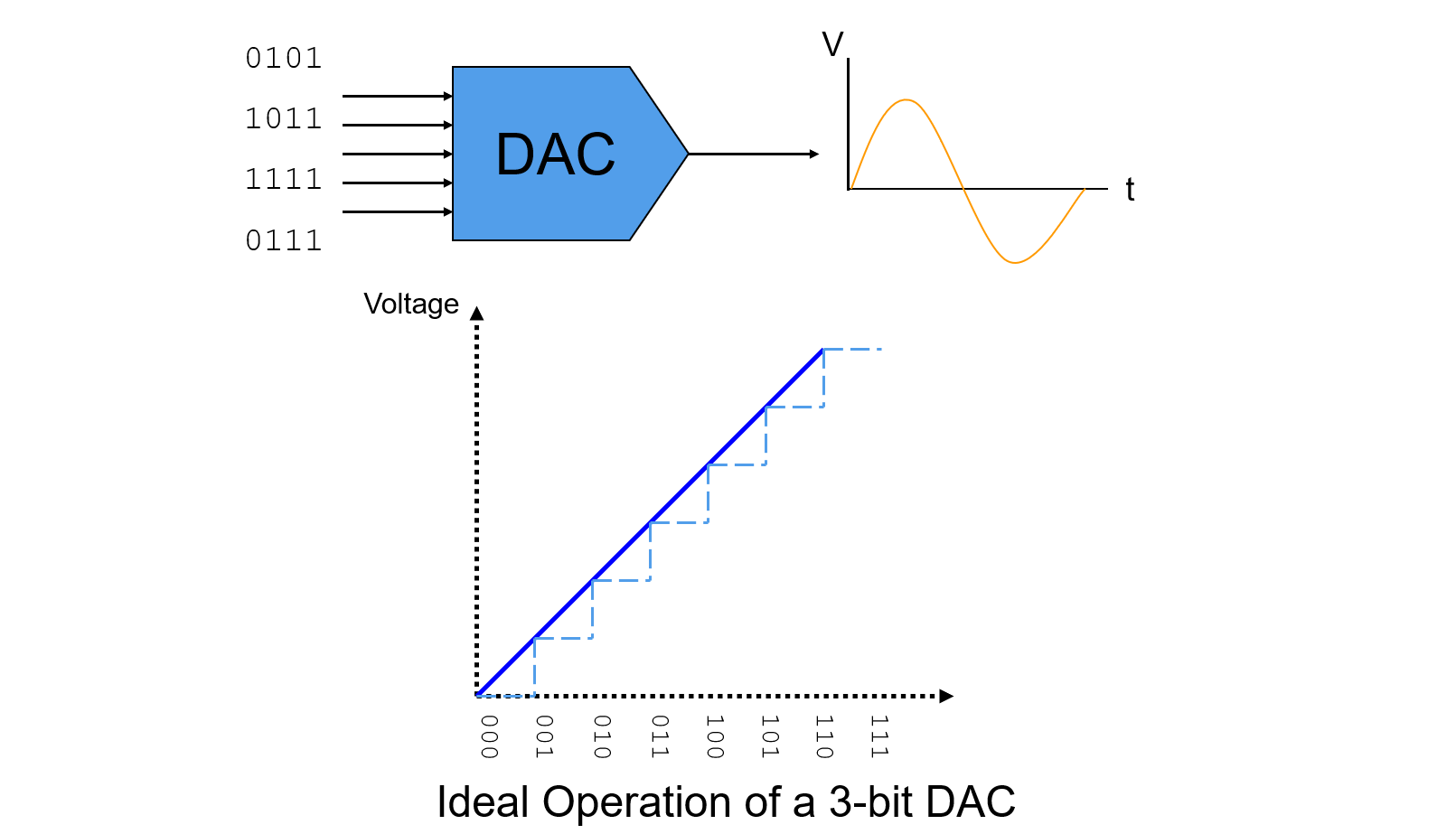
Digital to Analog Converter (ADC) is a device to converts a sequence of digital input data into analog signals.
Static Parameters
DAC's static parameters mainly contain:
- Zero Scale Output
- Full Scale Range (FSR)
- LSB Size
- Offset Error
- Gain Error
- Differential Non-Linearity Error (DNE or DNL)
- Integral Non-Linearity Error (INE or INL)
Zero Scale Output
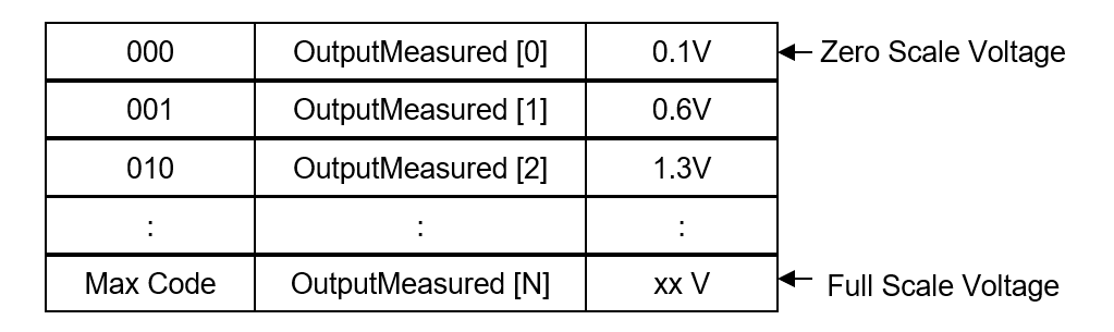
Zero Scale Output is the measured output value when the zero/null level digital input code is presented to the DUT.
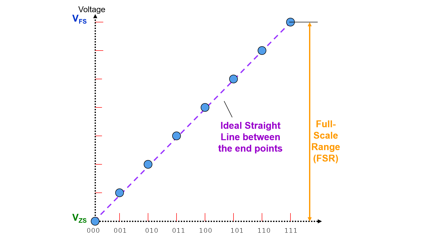
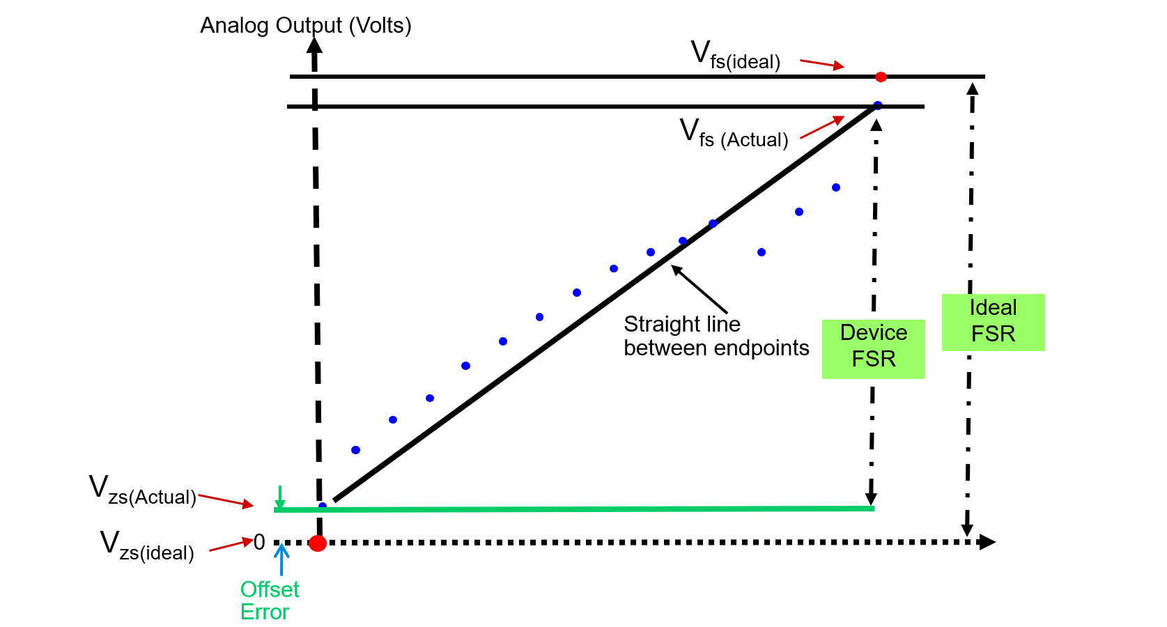
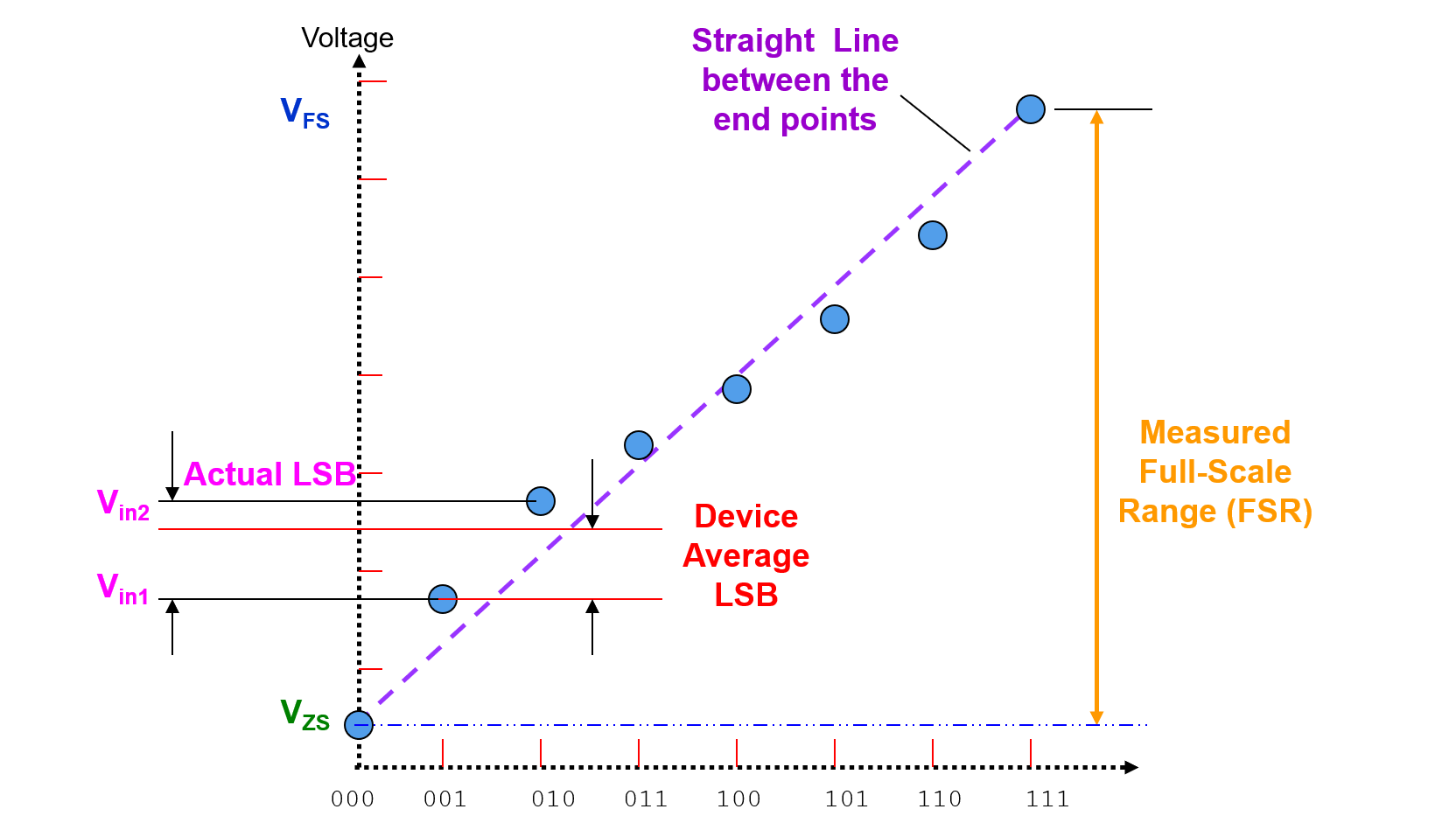
Full Scale Range (FSR)
Range of DAC output voltage between the minimum (\(V_{ZS}\)) and maximum (\(V_{FS}\)) analog outputs is called Full Scale Range (FSR):
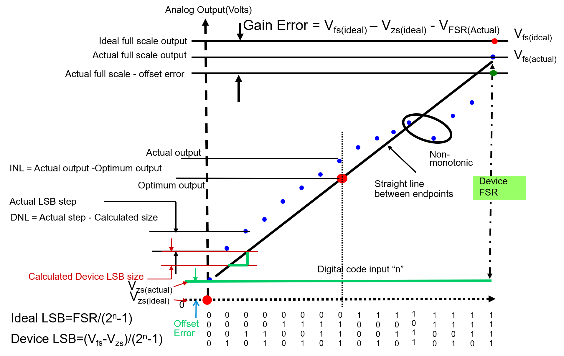
LSB Size
Average change in voltage when in between the input codes is defined as LSB:
Offset Error
Offset Error (Zero-Scale Error) is the voltage difference between ideal and actual offset (initial) points.
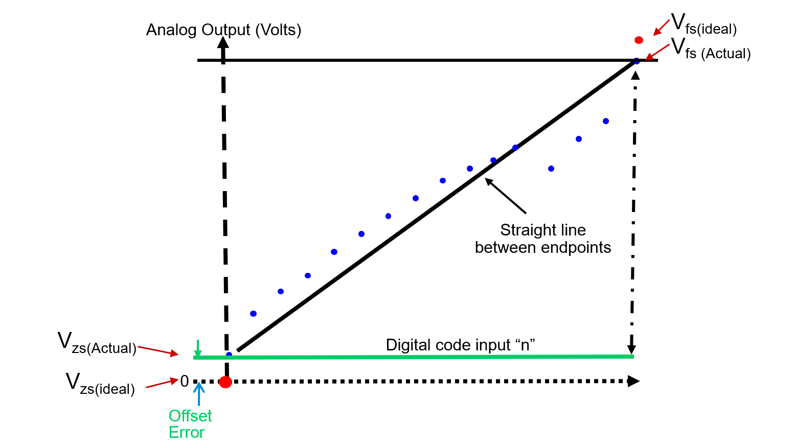
Gain Error
Gain Error is the voltage difference between ideal and actual gain points on the transfer function.
Where
Differential Non-Linearity Error (DNL)
Differential Non-Linearity Error (DNL) is the difference in the output voltage at a specific, compared to the output at the previous input, then minus one device LSB:
where \(V_{in2}\) is the voltage of the upper transition, \(V_{in1}\) is the lower.
DNL is a measure of "small-signal" linearity error. Measurement of DNL is made from one step to the next, not each step to the ideal value.
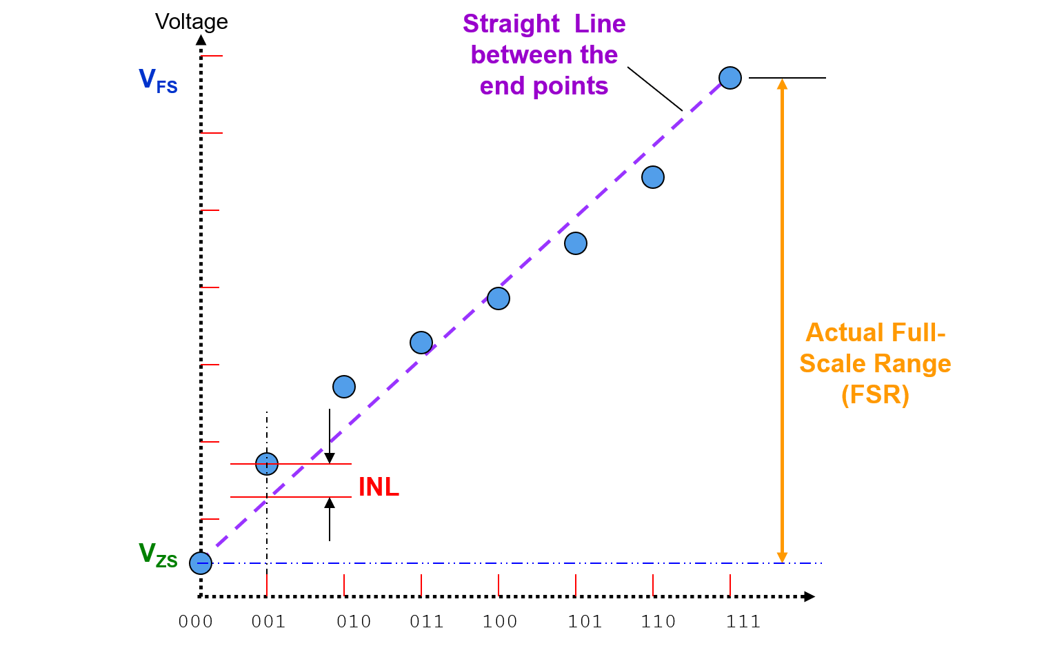
Integral Non-Linearity Error (INL)
Integral Non-Linearity Error (INL) is the cumulative effect of all differential non-linearity values.It is a measure of "large-signal" linearity error. INL at any point along the curve is the deviation of the ideal linearity line.
Also, INL can also be expressed as a function of DNL:
How to Test Static Parameters
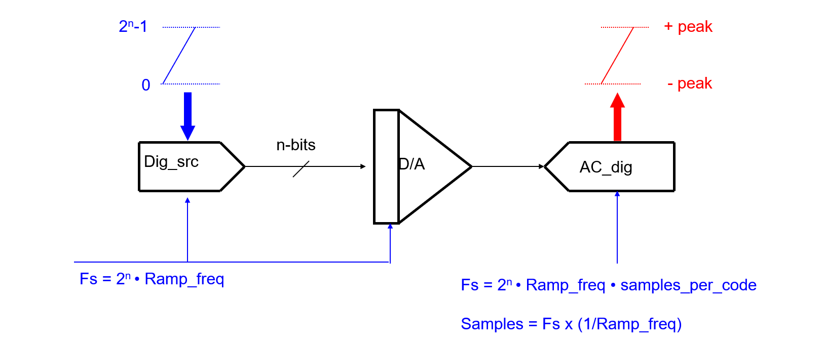
Test System Setup
Test system setup for DAC static parameter tests:
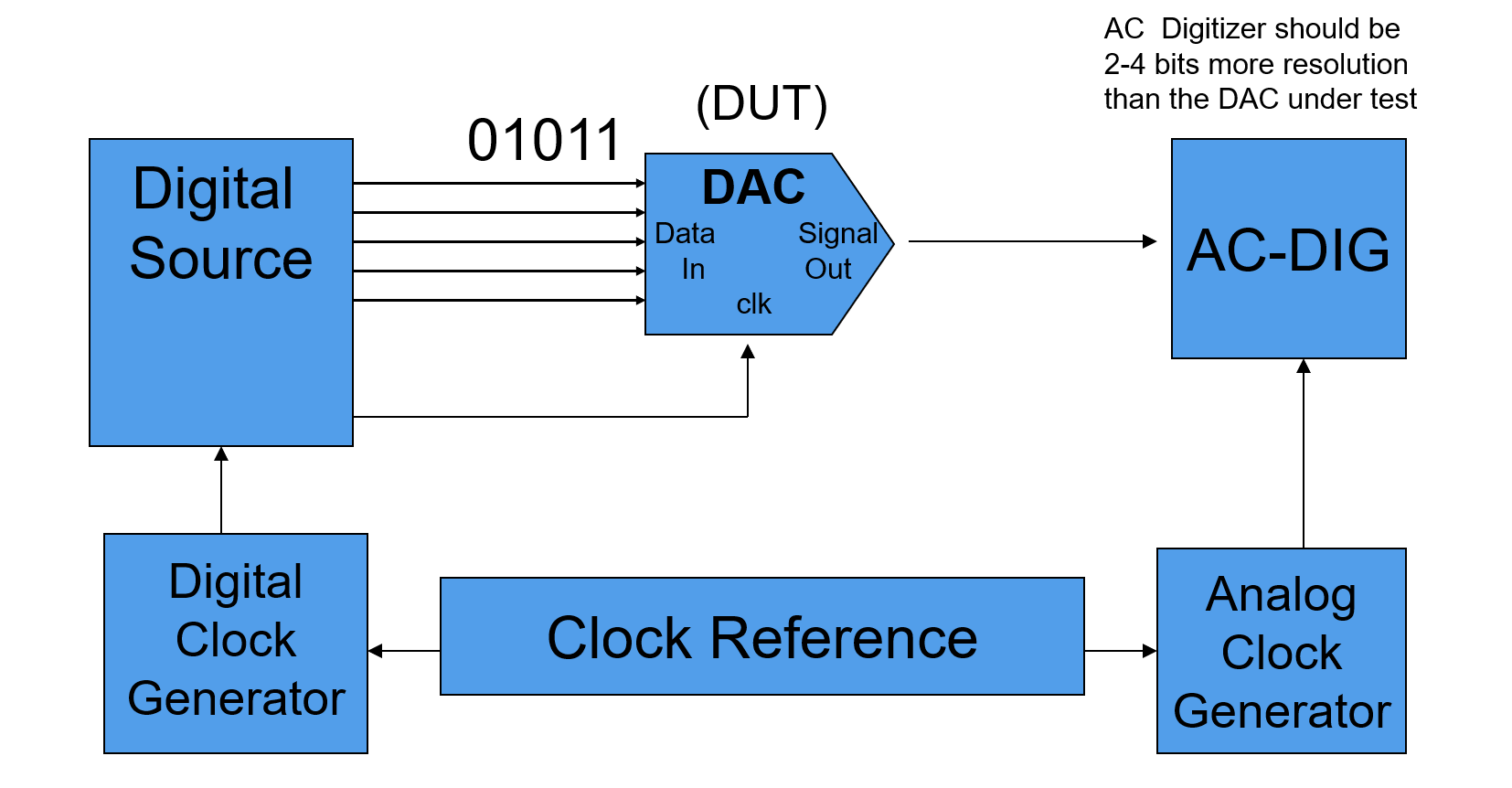
Block diagram of signal setup:
Tests Concept
Procedure of testing the static parameters of an DAC DUT is listed below.
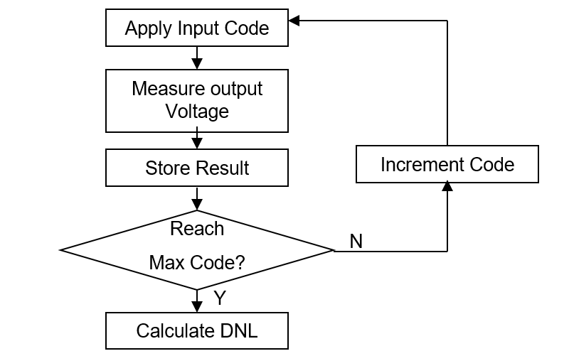
1. Measure the output voltage by applying the digital data inputs from Zero Scale to Full Scale
2. Calculate DNL for each input code
Where
3. Get the max and min DNL
4. Calculate for INL for each step
5. Get the max and min INL
References & Acknowledgements
- Fundamentals of Testing Using ATE
- The-Fundamentals-of-Mixed-Signal-Testing_Brian-Lowe
Original: https://wiki-power.com/
This post is protected by CC BY-NC-SA 4.0 agreement, should be reproduced with attribution.