Semiconductor Testing Fundamentals - OS Testing
Open and Short Testing (OS), also known as continuity or contact testing, is used to verify the electrical connectivity of all the pins of the testing system and the device under test (DUT), without causing a short circuit with other pins or the power supply (ground). OS testing quickly identifies electrical and physical defects in the DUT, such as pin shorts, missing bond wires, electrostatic damage to pins, and manufacturing defects. It can also uncover issues related to testing components, such as ProbeCards or the socket contact of the device.
The OS testing process relies on the protection diodes connected to VDD and ground. Generally, there are two testing methods: one involves applying current with a PMU to measure voltage, and the other uses a functional test method to provide VREF, creating a dynamic load current for voltage measurement.
OS Testing - Static Method
Serial/parallel static testing in OS essentially involves applying current to measure voltage. This current causes one of the protection diodes to forward bias, allowing abnormal open or short circuits to be detected by measuring the forward voltage drop. The test schematic for applying positive current to forward bias the power supply diode is shown below:
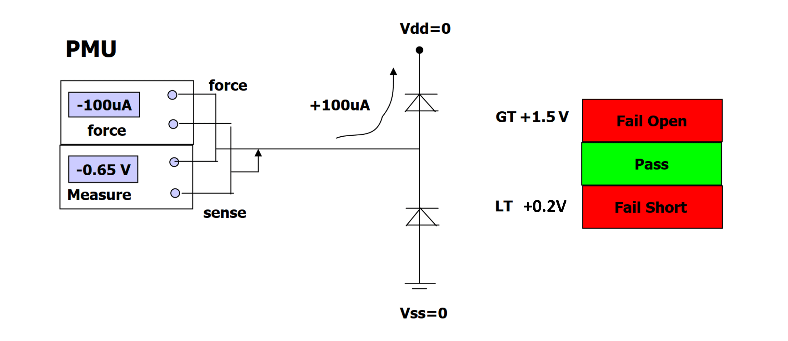
The test procedure is as follows:
- Ground all pins of the DUT, including power and ground.
- Apply current (approximately 100µA) to the pins using a PMU.
- Measure the pin voltage:
- Higher than VOH (+1.5V): Fail (Open)
- Lower than VOL (+0.2V): Fail (Short)
- Other ranges (forward voltage drop, e.g., 0.65V): Pass
The test schematic for applying negative current to forward bias the ground diode is shown below:
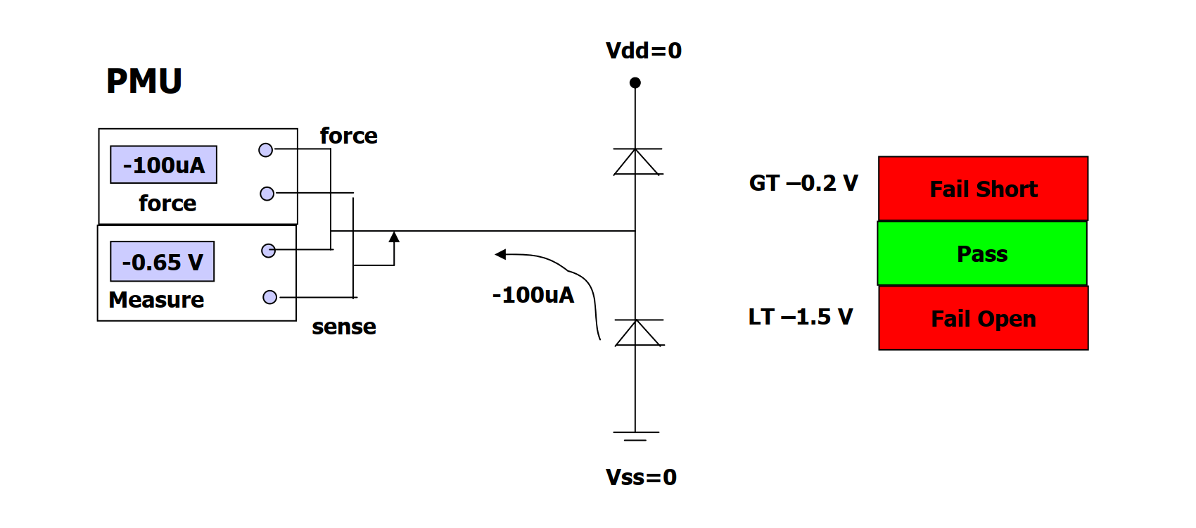
The test procedure is as follows:
- Ground all pins of the DUT, including power and ground.
- Apply current (approximately -100µA) to the pins using a PMU.
- Measure the pin voltage:
- Higher than VOH (-0.2V): Fail (Short)
- Lower than VOL (-1.5V): Fail (Open)
- Other ranges (forward voltage drop after forward bias, approximately -0.65V): Pass
Since the PMU provides constant current, voltage clamps need to be set to limit the voltage generated during open pin testing; otherwise, the voltage would become infinite. If the voltage clamp is set at 3V, then when a pin is open, the test result will be 3V.
This method is limited to testing signal IO pins and cannot be used for testing power supply pins. Although power supply pins can also be tested in open circuit conditions, their internal structure is different, requiring different test limits to be set.
In summary, the characteristics of OS static testing are as follows:
- Serial testing examines one pin at a time, with a simple process but low efficiency, suitable for DUTs with few pins.
- Parallel testing requires a testing system with PPMU but cannot detect adjacent pin shorts. A solution is to conduct two separate tests (e.g., test pins 1357 in the first round, and pins 2468 in the second).
- Application of current and measurement of voltage.
References and Acknowledgments
- "The Fundamentals Of Digital Semiconductor Testing"
- "DC Test Theory"
Original: https://wiki-power.com/ This post is protected by CC BY-NC-SA 4.0 agreement, should be reproduced with attribution.
This post is translated using ChatGPT, please feedback if any omissions.