Basic Electronic Components - Diode
Voltage-Current Characteristics:
- Voltage drop when conducting is approximately 0.7 V (for LEDs, it's around 1-2 V with a current of 5-20 mA).
- It does not conduct in reverse bias, but if the reverse breakdown voltage is exceeded, it will conduct (exceeding the maximum reverse voltage may damage it).
- It does not conduct with very low forward voltage (it only conducts when the voltage is above 0.5 V).
Main Parameters of Diodes
- Maximum Forward Current (\(I_F\)): Represents the maximum forward average current allowed for long-term operation. Exceeding this limit may result in overheating and damage.
- Maximum Reverse Working Voltage (\(U_R\)): The maximum reverse voltage that can be applied without breakdown (usually half of the breakdown voltage).
- Reverse Current (\(I_R\)): The reverse current when it's not in breakdown; lower values indicate better conductivity.
- Maximum Operating Frequency (\(f_M\)): The upper cutoff frequency. Beyond this frequency, the diode's one-way conductivity may not be effectively maintained due to junction capacitance.
Diode Classification
Types:
- Rectifier Diodes
- Standard Diodes: Relatively slow recovery speed, not suitable for high-frequency circuits.
- Fast Recovery Diodes
- Schottky Diodes: Used in scenarios with voltages less than 200V.
- Zener Diodes: Sustain breakdown and are used in low-power applications.
- Transient Voltage Suppressors (TVS): Designed for high-power scenarios.
Rectifier Diodes
Usage: Utilize one-way conductivity to convert AC voltage into pulsating DC.
Fast Recovery Diodes (FRD)
The structure and function of fast recovery diodes are similar to rectifier diodes. Rectifier diodes are used in low-frequency applications below 500 Hz, while FRDs are used in high-frequency switching applications ranging from a few kilohertz to 100 kHz. As a result, FRDs have very short reverse recovery times (trr), which are crucial for high-speed switching. Standard rectifier diodes typically have trr in the range of microseconds to tens of microseconds, while FRDs have trr in the range of tens of milliseconds to hundreds of milliseconds, about 1/100th of standard rectifier diodes. They are applied in switch-mode power supplies, inverters, DC/DC converters, and more.
Voltage Regulator (Zener) Diodes
Definition: Diodes that can maintain a stable voltage.
Zener diodes utilize the reverse characteristics of the PN junction. They sustain breakdown and provide a constant voltage, making them suitable for low-power applications.
Conditions for Voltage Regulation:
- Operating in the reverse breakdown state.
- Reverse voltage greater than the regulation voltage.
Parameters of Zener Diodes
- Regulation Voltage (\(U_Z\)): Represents the reverse breakdown voltage at a specified current for a given Zener diode model; it is a fixed value.
- Reverse Current (\(I_Z\)): The reference current when operating in the regulation state; the regulation effectiveness decreases when the current falls below this value, also known as \({I_Z}_{min}\).
- Rated Power Dissipation (\(P_{ZM}\)): Equal to the product of the regulation voltage (\(U_Z\)) and the maximum regulation current (\(I_{ZM}\)). Exceeding this value may result in overheating. Higher current leads to better regulation, as long as it does not exceed the rated power.
Basic Voltage Regulation Circuit:
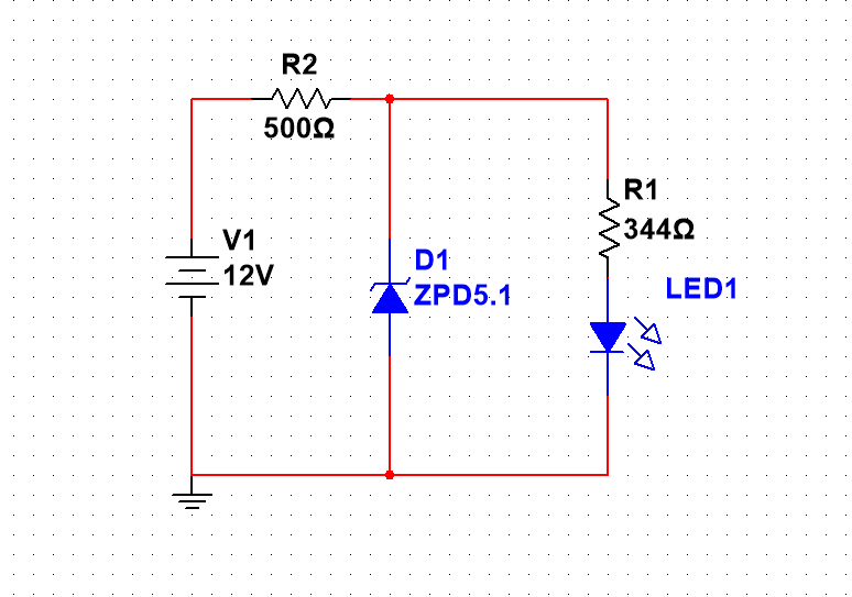
Selection of Current Limiting Resistor:
In the voltage regulation circuit, a current-limiting resistor is connected in series to protect the Zener diode (to drop the voltage difference between the input voltage and the regulation voltage). The voltage across the resistor is the difference between the input voltage and the regulation voltage, and the current is the sum of the Zener diode's \({I_Z}_{min}\) and \({I_Z}_{max}\), plus the total load current.
Transient Voltage Suppressors (TVS)
TVS diodes are designed to protect sensitive components from transient high-energy surges. TVS diodes come in unidirectional and bidirectional types. Unidirectional TVS diodes have characteristics similar to Zener diodes, while bidirectional TVS diodes are equivalent to two Zener diodes connected in reverse.
TVS diodes are connected in parallel in the circuit, and under normal conditions, current does not flow through the TVS branch. TVS exhibits the unidirectional conductivity of a diode:
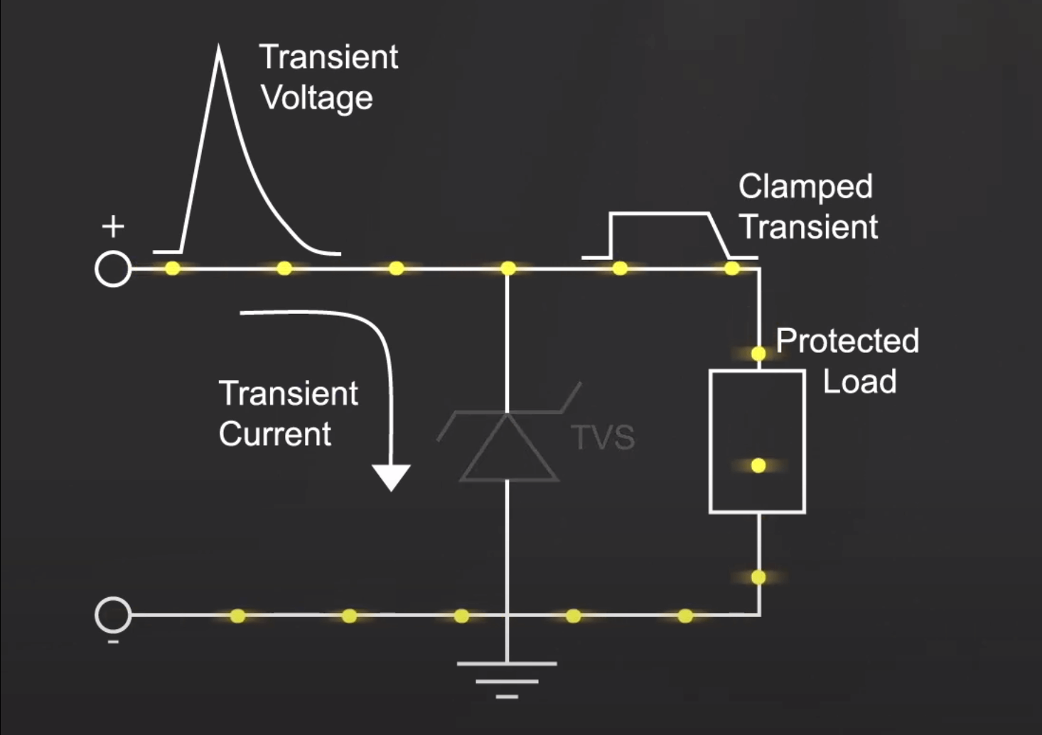
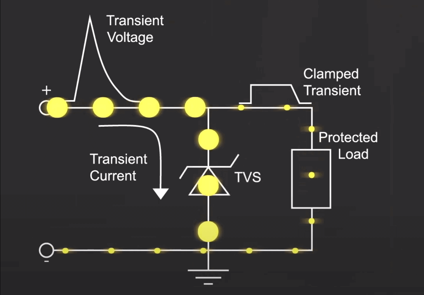
When an overvoltage occurs, the TVS enters breakdown and diverts the current to ground, keeping the voltage across the subsequent circuit at the clamping voltage of the diode:
Applications:
- Placed on signal and power lines to protect against electrostatic discharge, AC surges, or noise.
- Can handle pulses exceeding 10,000 V and 60 A for 10 ms, preventing component damage or interference caused by bus switching.
- Positioned between signal lines and ground to shield data and control lines from noise interference.
Main Parameters of TVS Diodes:
- Reverse Breakdown Voltage (VRWM) and Reverse Leakage Current (IR): The reverse breakdown voltage (VRWM) represents the highest voltage at which the TVS diode does not conduct, and at this voltage, there is only a minimal reverse leakage current (IR).
- Breakdown Voltage (VBR): The voltage at which the TVS diode begins to conduct when subjected to a specified test current; this voltage serves as an indicator of the diode's conduction.
- Peak Pulse Current (IPP): The maximum peak current allowed to pass through the TVS diode for a 10/1000μs waveform (typically around five times the peak current for an 8/20μs waveform). Exceeding this current value could result in permanent damage. In the same series, diodes with higher breakdown voltages allow smaller peak pulse currents, typically ranging from a few amps to tens of amps.
- Maximum Clamping Voltage (VC): The voltage across the TVS diode when it carries the peak pulse current IPP.
- Peak Pulse Power (Pm): \(Pm=IPP*VC\). Under a given maximum clamping voltage, a higher power dissipation (PM) indicates a greater surge current handling capability. Conversely, at a given power dissipation (PM), a lower clamping voltage offers higher surge current handling capacity.
- Steady-State Power (P0): TVS diodes can also be used as voltage-regulating diodes, in which case steady-state power is employed.
- Junction Capacitance (Cj): Similar to varistors, TVS diodes have significant junction capacitance (Cj), and unidirectional diodes have larger Cj values than bidirectional ones. The higher the power rating, the larger the capacitance, and junction capacitance affects the response time of TVS diodes.
Differences between TVS Diodes and Zener Diodes (Voltage Regulators):
TVS diodes absorb high overvoltages in a short time to protect downstream circuits, while Zener diodes clamp the input voltage to a constant level and provide this clamped voltage to downstream circuits.
Switching Diodes
Customized diodes designed for switching applications, with short cutoff/conduction switching times to prevent reverse current from damaging precision components.
Example:
The 1N4148 diode shown in the diagram serves a protective function. When a negative voltage is applied to the right side, it can conduct to ground, protecting the three-terminal voltage regulator.
Schottky Barrier Diodes (SBD)
Schottky barrier diodes combine semiconductor and metal, rather than using PN junctions (trr lengthens with temperature). Due to their low forward voltage and short reverse recovery time, they are suitable for high-speed switching applications.
Current-Voltage characteristics of Schottky barrier diodes:
Forward Bias and Reverse Bias
- Forward Bias: Refers to connecting the P side to a higher potential and the N side to a lower potential, allowing current to flow in the direction of the PN junction, demonstrating unidirectional conductive properties.
- Reverse Bias: In contrast, it involves the flow of reverse current from the N region to the P region. In general, it is considered that the PN junction in reverse bias does not conduct and is essentially in the cutoff state.
Common Packages
| Package Name | Remarks |
|---|---|
| DO-214AC/SMA | Current Rating: 2 A |
| DO-214AA/SMB | Current Rating: 4 A |
| DO-214AB/SMC | Current Rating: 5 A |
| DPAK/D2PAK |
References and Acknowledgments
- Diode Selection Guidelines (For Reference Only)
- Discrete Semiconductor Devices - Chapter II: Diodes
- TVS Diode Performance and Selection
- Electronic Engineer's Notebook: Diode Selection Guide
Original: https://wiki-power.com/
This post is protected by CC BY-NC-SA 4.0 agreement, should be reproduced with attribution.This post is translated using ChatGPT, please feedback if any omissions.