RF - Resonant Circuit - Resonance of Lossless Components
In previous chapters, we mentioned resonance in parasitic components of basic devices. Now let's study the causes of resonance and how to utilize it.
Resonance of Lossless Components
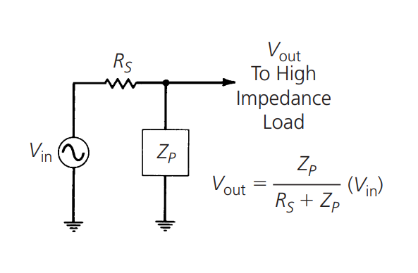
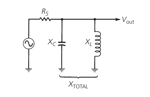
From the voltage division rule in the above figure, we can see that when an impedance component with impedance \(Z_p\) is placed at the output of a generator with internal resistance \(R_s\), the maximum output voltage that can be achieved by this circuit is:
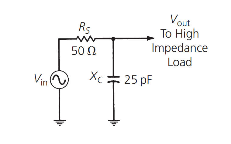
Therefore, \(V_{out}\) is always smaller than \(V_{in}\). If \(Z_p\) is an impedance that is frequency-dependent (such as capacitive or inductive reactance), then \(V_{out}\) will also be frequency-dependent, and the ratio of \(V_{out}\) to \(V_{in}\) is the gain of the circuit (or in this case, the loss), which also depends on the frequency. For example, let's take a 25pF capacitor as the impedance component:
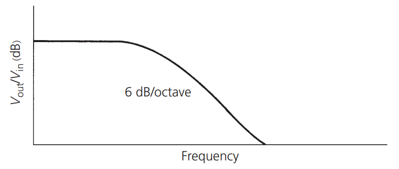
And plot the relationship between \(V_{out}/V_{in}\) (in dB) and frequency:
According to the following formula:
Where \(\frac{V_{out}}{V_{in}}\) represents the loss in dB; \(R_s\) represents the source impedance; \(X_C\) represents the capacitive reactance, \(X_C=\frac{1}{j\omega C}\).
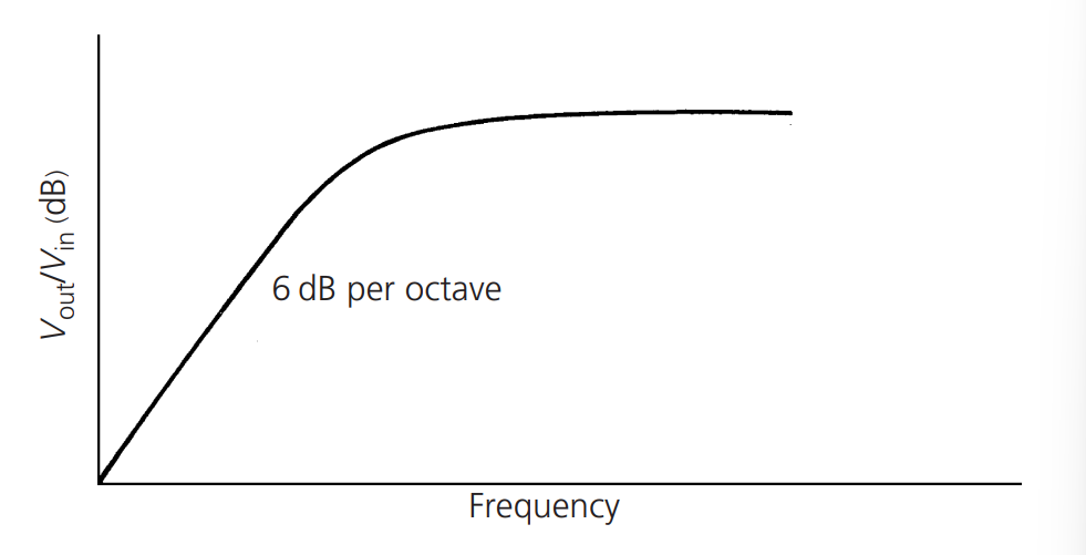
The loss of this RC circuit increases with increasing frequency. This forms a simple low-pass filter. It should be noted that for every doubling of frequency, the attenuation slope decreases at a rate of 6 dB. This is caused by the presence of a single reactive component in the circuit. As we will see later, for each significant reactive component added to the circuit, the attenuation slope will increase by an additional 6 dB.
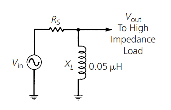
If we replace the capacitor in the circuit with a 0.05µH inductor:
We can plot the following curve:
Based on the following formula:
Where \(X_L\) represents the inductive reactance, \(X_L=j\omega L\).
Here, a simple high-pass filter with an attenuation slope of 6 dB/octave is formed.
Using the formulas mentioned earlier, we can plot the frequency response of two independent and opposite reactive components. If we combine the inductor and capacitor at the source end to form an LC circuit:
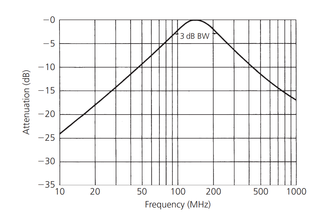
We will obtain the following curve:
Calculated based on the following formulas:
If expressed in dB, it can be represented as:
In the above equation, as we approach the resonant frequency of the tuned circuit, the slope of the resonance curve increases to 12 dB/octave. This is because both reactive elements are changing at a rate of 6 dB/octave and in opposite directions. However, as we move away from resonance in either direction, the curve stabilizes again to a slope of 6 dB/octave. This is because only one reactive element is playing a role, while the other presents a very high impedance to the circuit at these frequencies and can be ignored.
RLC filters can be used to select a narrow range of frequencies from the total spectrum of ambient radio waves, acting as bandpass filters.
References and Acknowledgements
- "RF-Circuit-Design(second-edition)_Chris-Bowick"
Original: https://wiki-power.com/ This post is protected by CC BY-NC-SA 4.0 agreement, should be reproduced with attribution.
This post is translated using ChatGPT, please feedback if any omissions.