Power Supply Topology - Linear Regulator
The function of a linear regulator is to convert a stable or unstable input voltage into a stable output voltage. During normal operation, even if there is a significant fluctuation in the input voltage, the output voltage can still remain stable.
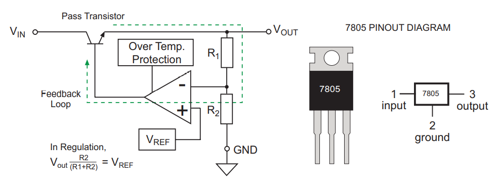
Principle of Linear Regulator
Most linear regulators are controlled in a closed loop. To obtain the desired output voltage, we can adjust the ratio of R1/R2 so that the voltage at the inverting input of the amplifier is equal to the reference voltage \(V_{ref}\) at the non-inverting input of the amplifier. The function of the error amplifier feedback loop is to keep the voltage difference between the two inputs at 0.
The principle is that if the load decreases / input voltage increases, the output voltage will increase, the voltage at the inverting input of the amplifier will be higher than the voltage at the non-inverting input \(V_{ref}\), the voltage at the output of the error amplifier will be negative, the voltage at the base of the pass transistor will decrease, and ultimately the output voltage of the transistor will also decrease. Conversely, if the load increases / input voltage decreases, the voltage at the inverting input of the amplifier will decrease, below the voltage at the non-inverting input \(V_{ref}\), the voltage at the base of the pass transistor will increase, resulting in an increase in the output voltage to compensate for the originally expected decrease in the output voltage. The feedback loop can simultaneously adjust the voltage changes caused by input voltage variations (line regulation) and load variations (load regulation).
Efficiency of Linear Regulator
The efficiency of a linear regulator refers to the ratio of the output power \(P_{out}\) to the input power \(P_{in}\):
Where,
\(I_{q}\) is the static current under no load.
Low Dropout Linear Regulator - LDO
In a conventional linear regulator, a bipolar transistor is used as the current amplifier. Due to the formation of a Darlington circuit, there is a certain voltage drop.
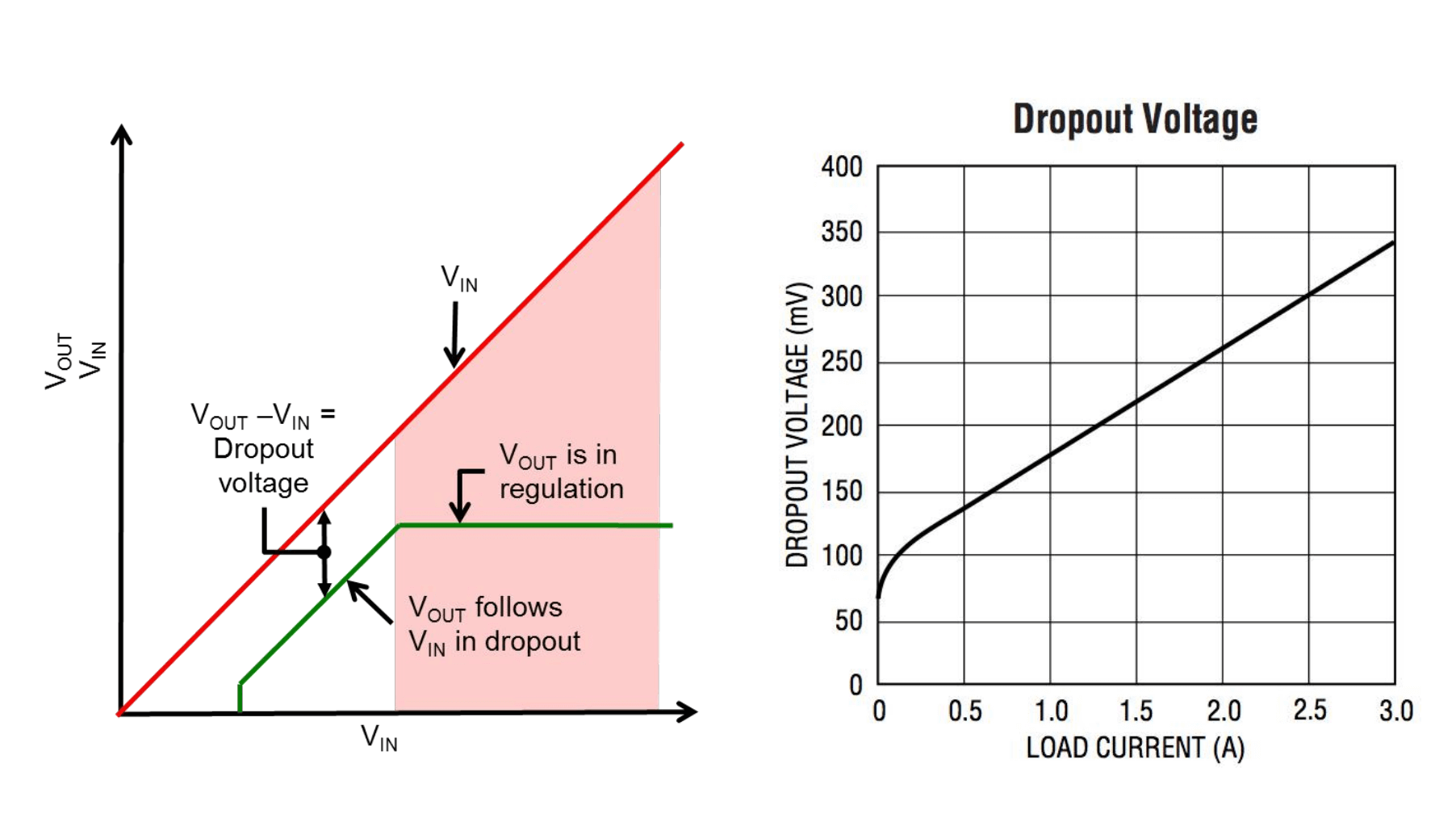
If a P-channel field-effect transistor is used instead of a bipolar transistor, a so-called low dropout linear regulator (LDO) is obtained, which has a dropout voltage of only a few hundred millivolts.
Because the dropout voltage of a field-effect transistor depends only on its forward conduction voltage (equivalent to \(R_{ds}*I_{load}\)). Usually, the resistance \(R_{ds}\) is very small, so the dropout voltage is also very low.
Advantages and Disadvantages, Applications
Advantages
- Simple and inexpensive circuit
- Low output noise
- High isolation from noise
- Fast transient response
Disadvantages
- Requires a certain dropout voltage to regulate, so it can only be used for step-down applications.
- In cases where the dropout voltage is relatively large, the conversion efficiency is low, and the losses are dissipated as heat, affecting the stability and reliability of the circuit board.
- Emphasizes power above all else, even when the load circuit does not require a large current. The consequence of this is that all components work at full load even when not necessary, resulting in much higher heat generation.
- In cases where the dropout voltage is insufficient, significant ripple may occur.
Applications
- Analog circuits, clock generation circuits, etc., where strict requirements for power supply noise are needed.
- Digital circuit power supply scenarios where low current and power conversion efficiency have little impact.
References and Acknowledgments
- Please raise your hand to answer, what is the difference between LDO and DC-DC?
- Successful Application of Low Dropout Regulators (AN-1072) in Systems
- Fundamental Knowledge of Linear Regulators
- LDO Basics: Principles and Applications
- [Handbook and Practical Tips for DC-DC Converters]
-
Original: https://wiki-power.com/
-
This post is protected by CC BY-NC-SA 4.0 agreement, should be reproduced with attribution.
This post is translated using ChatGPT, please feedback if any omissions.