Power Supply Design - Solution Determination
Requirements to Consider in Power Supply Design
- Functionality: Input voltage, current (range of variation); output voltage, current, and meeting overall power specifications to achieve maximum system conversion efficiency.
- Performance: Ripple size on the output voltage, load capacity, efficiency, heat generation, and more.
- Cost: Overall system cost, considering core components and peripheral devices (inductors or coils, capacitors, MOSFET drivers, etc.).
- Space: Considerations for space dimensions, placement, heat dissipation, interference, and limitations.
How to Choose a Power Supply Solution
Common Power Supply Types
- Linear Regulators
- Three-terminal regulators
- Low-dropout regulators (LDO)
- Switching Regulators
- Non-isolated
- Buck (step-down)
- Boost (step-up)
- Buck-Boost (step-down/step-up)
- Cuk (two-stage inverting)
- SEPIC, ZETA (two-stage non-inverting)
- Isolated
- Forward
- Flyback
- Non-isolated
- Power Supply ICs
- Multiple outputs
- Charging ICs
Comparison of Linear and Switching Regulators
| Linear Regulators | Switching Regulators | |
|---|---|---|
| Efficiency | Relatively low (30% ~ 60%) | Relatively high (70% ~ 90%) |
| Regulation Mode | Only step-down | Step-down, step-up, step-up/step-down, inverting |
| Heat Generation | Relatively high | Relatively low |
| Size | Relatively large | Relatively small |
| Weight | Relatively heavy | Relatively light |
| Circuit Complexity | Simple | Relatively complex |
| Stability | Relatively high | Moderate |
| Transient Response | Fast | Slow |
| Noise | None | Present (requires noise mitigation measures) |
| Isolation | Non-isolated | Isolated |
| Application | Low current, low noise requirements, lower efficiency | High current, high efficiency requirements |
Visual Differences Between Linear and Switching Regulators
Analogously, consider the output voltage as the flow of water from a tap. In linear regulation, you adjust the tap to control the water flow according to your needs. For switching regulation, the tap only has two states: open and closed. Hence, it rapidly switches, altering the duty cycle to control the water flow.
Linear regulators employ a three-terminal transistor working in a linear mode to control current and achieve stable voltage output. This method is simple, provides high noise suppression (up to 60dB or 1000 times), but generally has lower efficiency. It requires a certain voltage difference between input and output for regulation and can only step-down. Linear regulators have a simple circuit, low ripple, and high power supply rejection ratio (PSRR), but the excess energy is dissipated as heat to limit the output voltage.
Switching voltage regulation takes advantage of the ability of inductive and capacitive components to store energy, allowing energy to be divided into segments and transmitted. These packaged energies are either stored in the magnetic field of an inductor or in the electric field of a capacitor. By controlling the switch, it ensures that each segment only delivers the energy needed for the load, resulting in relatively high efficiency. The benefits of switching voltage regulation include the ability to step down, step up, or invert the input voltage over a wide range while achieving high efficiency (some can reach over 95%). However, the drawback is that the peripheral circuitry is relatively complex, the selection of peripheral components is sensitive, and high-frequency switching signals can introduce significant interference and ripple in the output voltage.
Combining Switching and Linear Voltage Regulation
Considering the pros and cons of switching regulators and linear regulators, combining them (i.e., using switching regulation followed by linear regulation) can reduce output voltage ripple while improving efficiency.
Selection Based on Input and Output Voltage
- \(V_{in}>V_{out}\)
- Small voltage difference, low load current, low noise requirements — LDO
- Large voltage difference, high load current, not very noise-sensitive — Buck converter
- Low load current, not noise-sensitive, high efficiency required — Charge pump
- \(V_{in}<V_{out}\)
- Low power — Charge pump
- Large voltage difference, high load current, not very noise-sensitive — Boost converter
- \(V_{in}\) has a wide variation range, possibly greater or less than \(V_{out}\)
- Low power — Charge pump
- High load current, not very noise-sensitive — Buck-Boost converter
- If isolation is required
- Choose isolated topologies like flyback, forward, push-pull, full bridge, etc.
Component Selection
Factors to consider when selecting components:
- Functionality: Whether it meets the input/output voltage and current requirements
- Performance: As low ripple and noise as possible, and as high conversion efficiency as possible
- Price: Overall system cost
- Supply Channels: Ease of procurement
You can use tools provided by power chip manufacturers to assist in component selection, such as TI Reference Designs.
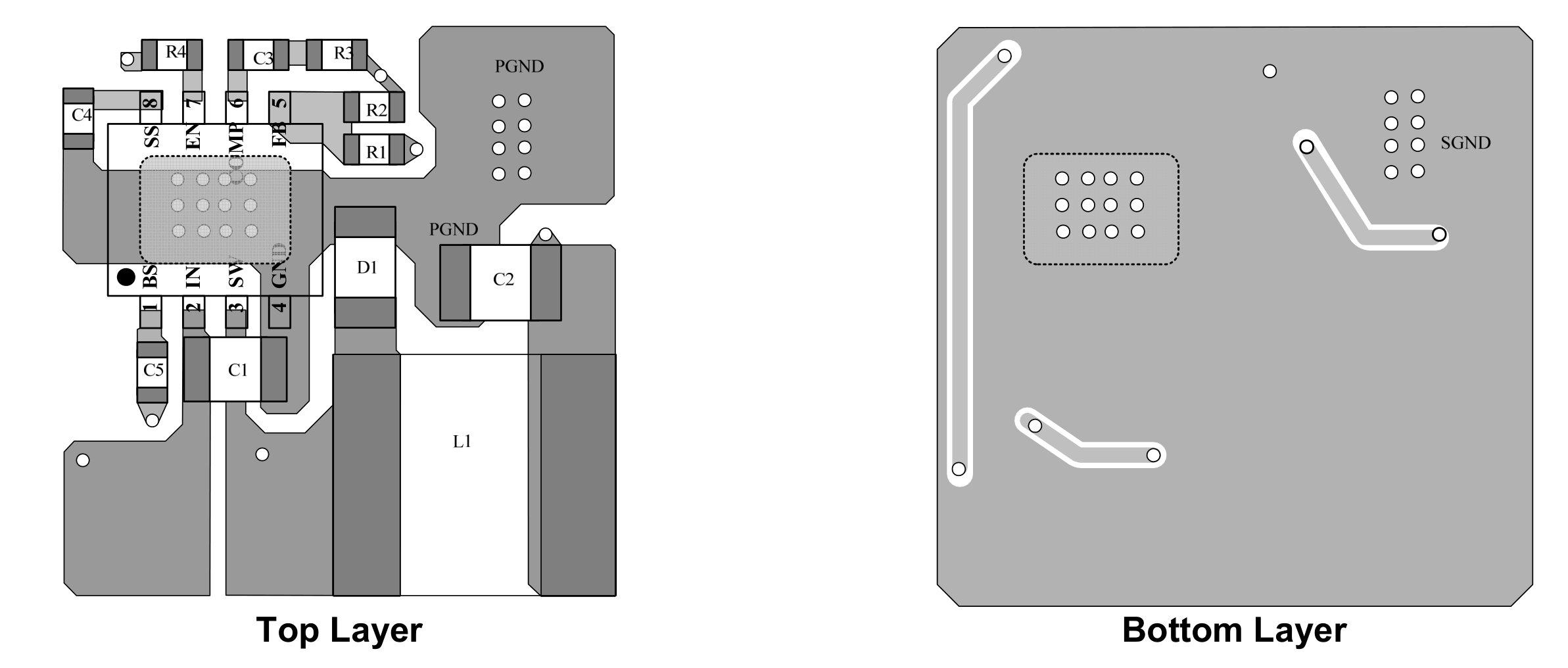
PCB Layout and Routing
For LDOs, heat dissipation is a critical factor affecting performance and stability, so heat dissipation should be considered when laying out the PCB. For DC-DC converters, consider the path of high current to avoid significant ripple, and ensure that feedback pins are not disturbed. Generally, you can refer to the layout provided in the datasheet, for example:
References and Acknowledgments
- Top 10 Voltage Regulators Preferred by Engineers Worldwide
- The Key 7 Steps in Switching Power Supply Design
- What You Need to Know About Switching Power Supplies
- Design Examples of Power Circuits in Electronic Products
- Power Supply and Management
- Comic Book Guide to Power Supplies - A Beginner's Delight!
- Guide to Selecting Low-Power Power Supply Chips for Single Board
Original: https://wiki-power.com/ This post is protected by CC BY-NC-SA 4.0 agreement, should be reproduced with attribution.
This post is translated using ChatGPT, please feedback if any omissions.