AirForce - A Motor Drive Module Filled with Spirit
The AirForce project is a motor drive combination kit, consisting of the integrated voltage-regulated mainboard, AirPort, and the dual-motor drive subboard, AirCraft. It allows for the flexible expansion of up to 16 motor drives according to your motor quantity requirements. Due to its compact size, robust performance, and high expandability, it has been aptly named Project AirForce.
Features:
- Compact size with convenient interface for wiring.
- Interfaces are not entirely enclosed in a black box, enhancing wiring capabilities.
- Does not excessively consume timer pins of the microcontroller (STM32).
Project Repository: linyuxuanlin/AirForceDVR
AirPort - Mainboard with Integrated Voltage Regulation
🚧
AirCraft - Dual Motor Drive Subboard
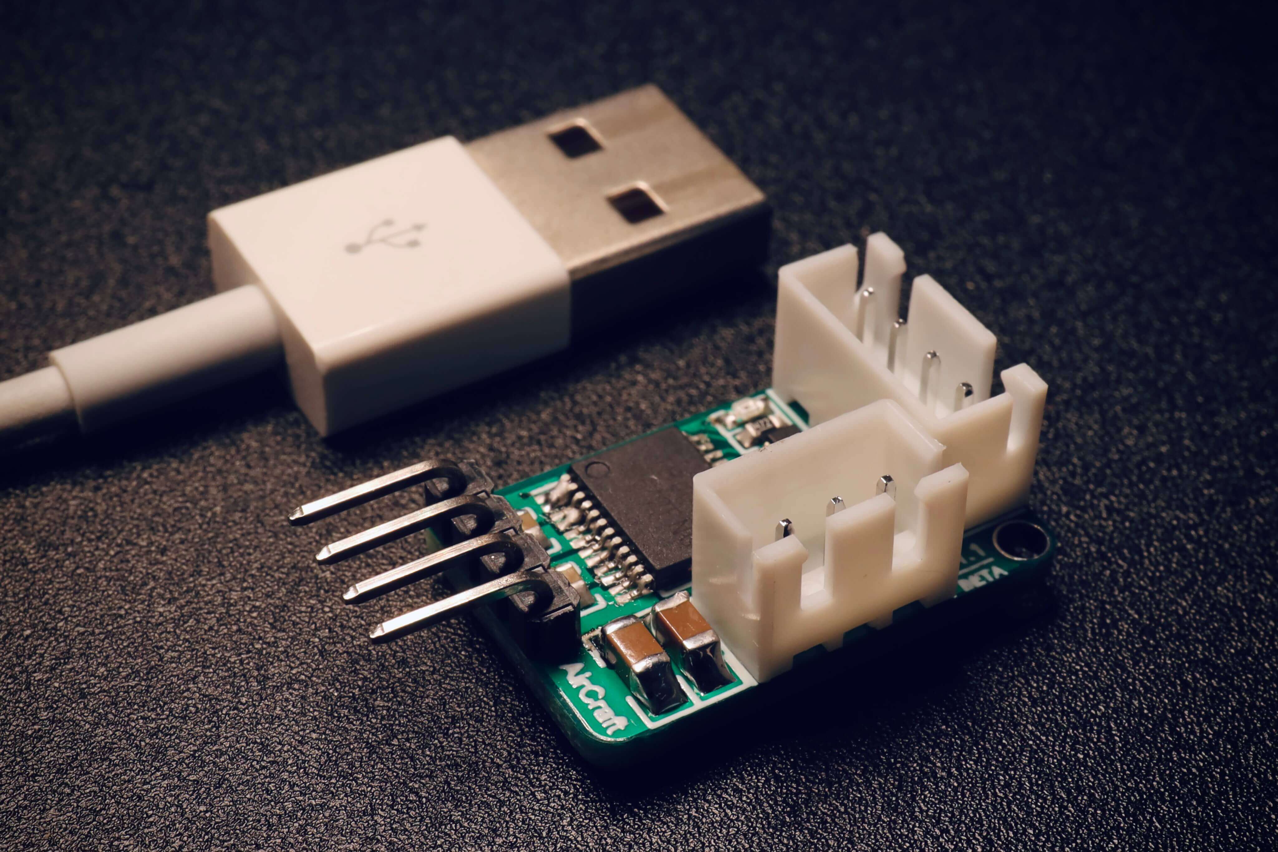
The AirCraft dual motor drive subboard is designed based on the TB6612FNG integrated drive chip, along with a logic control method. It only requires 4 pins (2 general-purpose + 2 PWM) to control dual motors (direction/speed). Compared to typical solutions on the market, it reduces the usage of two I/O pins, saving valuable resources on the main controller. As for the drive chip specifications, a single channel can handle a maximum continuous drive current of 1.2A, with peak values of 2A/3.2A (continuous pulse/single pulse), making it more than sufficient for driving motors commonly found on robots.
Product Specifications:
- Logical part input voltage VCC: 3.3~5V (default 5V).
- Drive part input voltage VM: 2.5~12V (default 12V).
- Number of motor drive channels: 2 channels.
- Maximum continuous drive current for a single channel: 1.2A.
- Startup peak: 2A/3.2A (continuous pulse/single pulse).
- Interface type: 2.54mm pitch pin header, XH2.54 socket.
- Module dimensions: 23.7 × 15.8 (mm).
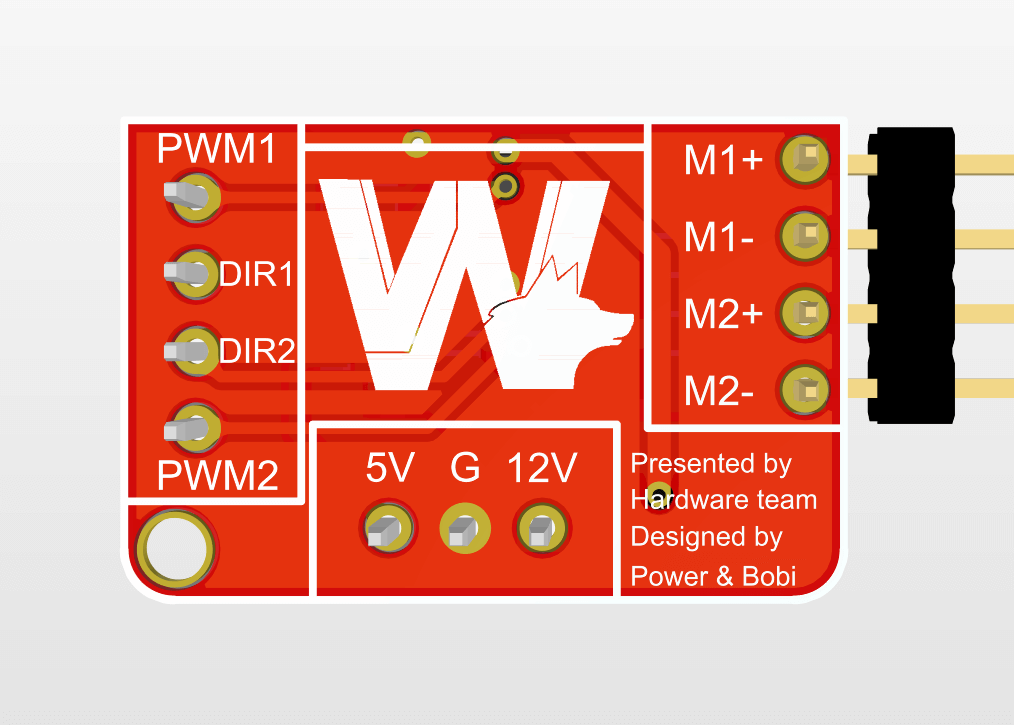
Pin Descriptions:
| Interface Group | Name | Function Description |
|---|---|---|
| Control Interface | PWM1 | Motor M1 speed control pin |
| Control Interface | DIR1 | Motor M1 direction control pin |
| Control Interface | DIR2 | Motor M2 direction control pin |
| Control Interface | PWM2 | Motor M2 speed control pin |
| Power Interface | 5V | Logic control section power |
| Power Interface | GND | Ground |
| Power Interface | 12V | Motor power |
| Motor Interface | M1+ | Motor M1 output 1 |
| Motor Interface | M1- | Motor M1 output 2 |
| Motor Interface | M2+ | Motor M2 output 1 |
| Motor Interface | M2- | Motor M2 output 2 |
Control Tutorial:
- Control Interfaces
- DIR1/DIR2: Inputs for forward and reverse control signals
- e.g., Setting DIR1 to 1 (high level) results in forward motion of the M1 motor; setting DIR1 to 0 (low level) results in reverse motion of the M1 motor.
- PWM1/PWM2: Enable pins for the two motors (adjustable using PWM for speed control).
- DIR1/DIR2: Inputs for forward and reverse control signals
- Power Interfaces: Connect to any power interface on the AirPort mainboard (or externally connect 12V and 5V inputs).
- Motor Interfaces: Connect to the input of the motors.
Dimensional Diagram:
🚧
References and Acknowledgments
Certainly, here is the translation:
[1] [2]
This post is translated using ChatGPT, please feedback if any omissions.