HAL Library Development Notes - GPIO
Basic Principles
GPIO stands for General Purpose Input Output.
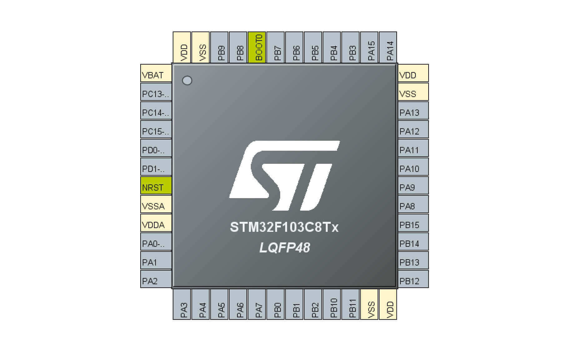
Taking the F103C8T6 chip as an example (in the above figure), all the pins except for the colored ones (power supply and certain functional pins) are called GPIO. This shows its versatility.
The function of GPIO is to input/output electrical signals. Let's take a look at its internal structure:
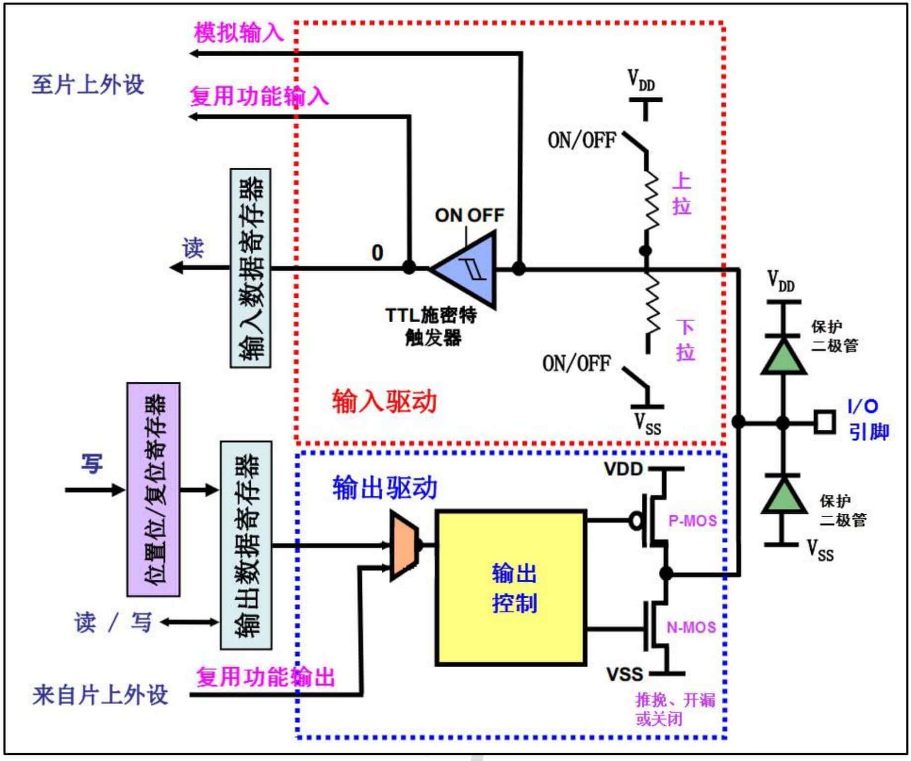
- The rightmost I/O pin is the physical pin of the chip. The upper and lower
protective diodescan prevent the chip from being burned by abnormal external voltages to some extent. - The red dashed box represents the input function (the chip reads external signals). The two switches with pull-up/pull-down resistors are used to implement pull-up/pull-down input functions. If both switches are not closed, it is called floating input (neither high nor low, without reference level). All three input modes mentioned above are digital (high/low level). In addition, there is an analog input function, which directly reads the analog value on the pin. (We will mention the multiplexing input function later).
- The blue dashed box represents the output function. There are four modes of output: push-pull, open-drain, multiplexing push-pull, and multiplexing open-drain.
Input/Output Modes
Input modes:
- Floating Input: Neither pull-up nor pull-down, this is the default mode after the STM32 is reset.
- Pull-Up Input: Close the switch of the pull-up resistor to keep the reference level always high, and trigger when the input signal is low.
- Pull-Down Input: Close the switch of the pull-down resistor to keep the reference level always low, and trigger when the input signal is high.
- Analog Input: In this mode, neither pull-up nor pull-down is used, and it does not pass through the TTL trigger. The STM32 directly reads the analog signal on the pin.
Output modes:
- Open-Drain Output: Open-drain refers to the drain of the N-MOS transistor (the pin above it). This mode only uses the N-MOS transistor below. We know that the MOS transistor is a voltage-controlled component. It can be understood as a water tap. When a low-level signal is input to the gate of the N-MOS transistor (the left pin), the N-MOS transistor conducts.
- Push-Pull Output: There are two modes of push-pull. In the first mode, a low-level signal is simultaneously applied to the gates of both MOS transistors, so the P-MOS transistor conducts while the N-MOS transistor cuts off, and the current flows from VDD to the external pin, making the pin high. In the second mode, a high-level signal is simultaneously applied to the gates of both MOS transistors, so the P-MOS transistor cuts off while the N-MOS transistor conducts, and the current flows from the external pin to the internal GND, making the pin low.
- Multiplexing Open-Drain
- Multiplexing Push-Pull
Commonly Used GPIO Function References
Read GPIO status, return high/low level:
Write GPIO status, write high/low level:
Toggle GPIO level:
Light up LED
Before proceeding to the next experiment, you need to configure various parameters such as serial port download and clock in CubeMX. Here, I won't go into details. Please refer to the article HAL Library Development Notes - Environment Configuration for the method.
Configuring GPIO in CubeMX
Set the corresponding GPIO pins for the LED as output and set the initial level.
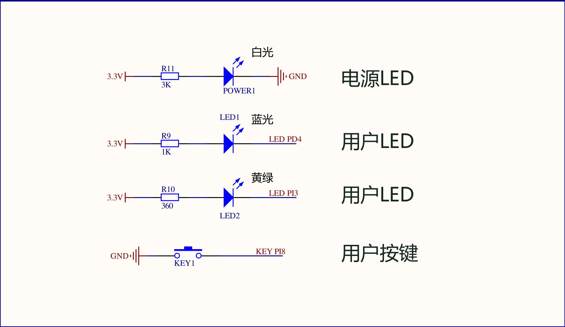
On my board, the PD4 and PI3 GPIO pins need to be set as outputs (GPIO_Output). If you want the LED to light up when powered on, according to the circuit schematic, set the initial level to low (Low).
Configuring GPIO in the Code
If the configuration is correct, the two user LEDs will light up as soon as power is applied.
To add a flashing effect, simply add a few lines of code in the user code section of the main loop:
/* USER CODE BEGIN 3 */

HAL_Delay(500);
HAL_GPIO_TogglePin(GPIOD, GPIO_PIN_4);
HAL_GPIO_TogglePin(GPIOI, GPIO_PIN_3);

}
/* USER CODE END 3 */
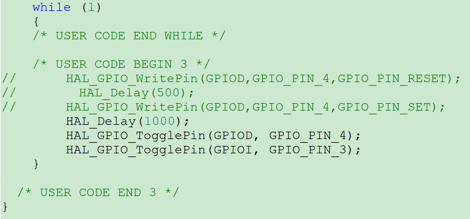
This will achieve the flashing effect.
Controlling LEDs with Buttons
After learning about GPIO output, let's learn about GPIO input mode using buttons.
Configuring GPIO in CubeMX
After configuring the GPIO port to which the LED belongs using the method mentioned above, according to the schematic diagram of the onboard button:
Set the GPIO (PI8) to input (GPIO_Input). According to the schematic diagram, select internal pull-up (Pull-up). Generate the code.
Configuring GPIO in the Code
Add the following code in the user code section of the main loop:
/* USER CODE BEGIN 3 */

if(HAL_GPIO_ReadPin(KEY1_GPIO_Port,KEY1_Pin)==0)
{
    HAL_Delay(100);
    if(HAL_GPIO_ReadPin(KEY1_GPIO_Port,KEY1_Pin)==0)
    {
        HAL_GPIO_WritePin(LED1_GPIO_Port,LED1_Pin,GPIO_PIN_RESET);
    }
}else{
    HAL_GPIO_WritePin(LED1_GPIO_Port,LED1_Pin,GPIO_PIN_SET);
}

}
/* USER CODE END 3 */
This will achieve the effect of turning on the LED when the button is pressed and turning it off when the button is released.
Many people are confused about the meaning of GPIO_PIN_SET and GPIO_PIN_RESET. In fact, the function of these two variables is simply to set the GPIO pin to high or low level. Whether the light is on or off depends on the circuit schematic.
In addition, the function of HAL_Delay(100) is to eliminate button bounce in the code. However, the HAL_Delay() function uses polling, which consumes resources and may cause the system to hang. In the next article, we will use hardware interrupts to solve this problem.
References and Acknowledgements
- 【STM32】STM32CubeMX Tutorial 2 - Basic Usage (Creating a Project to Light Up an LED)
- STM32CubeMX Practical Tutorial 2 - Button Control LED
Original: https://wiki-power.com/
This post is protected by CC BY-NC-SA 4.0 agreement, should be reproduced with attribution.This post is translated using ChatGPT, please feedback if any omissions.