Lora Communication - Based on Elecrow ATK-LORA-01 Module
The ATK-LORA-01 is a compact, low-power, energy-efficient, high-performance long-range Lora wireless serial module. The module is designed with the efficient ISM band RF SX1278 spread spectrum chip, operating in the frequency range of 410MHz to 441MHz, with a 1MHz frequency step for a total of 32 channels. It can be configured online via AT commands to modify various parameters such as serial port speed, transmission power, air speed, operating mode, and it also supports firmware upgrades.
Module Basic Specifications
- Operating Frequency: 410-441 MHz, 32 channels
- Industrial Frequency Band: Factory default at 433MHz, no licensing required
- Wireless Data Rate: Adjustable in 6 levels (0.3, 1.2, 2.4, 4.8, 9.6, 19.2Kbps)
- Communication Interface: TTL serial, UART serial, 8N1, 8E1, 8O1, with 8 available baud rates (default 9600, 8N1)
- Transmit Power: 100mW (20dB), adjustable in 4 levels (0-3), with approximately 3dBm increase or decrease per level
- Operating Voltage: 3.3-5V
- Operating Current: 2.3uA-118mA
- Transmit: 118mA (20dBm, 100mW, 5V voltage)
- Receive: 17mA (Mode 0, Mode 1), with a minimum of approximately 2.3uA (Mode 2+2S wake-up)
- Operating Temperature: -40~85°C
- Receiver Sensitivity: Up to -136dBm, with a transmission range of 3000 meters
- Dual 512 Circular FIFO
Interface Definitions
| Name | I/O Mode | Description |
|---|---|---|
| MD0 | Input | Configuration entry for parameter settings; when powered on, it enters firmware upgrade mode in conjunction with the AUX pin |
| AUX | ① Output; ② Input | ① Used to indicate the module's operational status and to wake up an external MCU; ② When powered on, it enters firmware upgrade mode in conjunction with the MD0 pin |
| RXD | Input | TTL serial input, connected to an external TXD output pin |
| TXD | Output | TTL serial output, connected to an external RXD input pin |
| GND | Ground | |
| VCC | DC 3.3~5V power input |
Please Note:
- The module's pin voltage level is 3.3V; for communication with a 5V microcontroller, level-shifting adaptation is required.
- The wireless serial module operates at TTL level, so it should be connected to a TTL-level MCU.
| Function | Description | Access Method |
|---|---|---|
| Configuration | Module Parameter Setup (AT Commands) | Power on, AUX floating, MD0 pulled high |
| Communication | Used for Wireless Communication | Power on, AUX floating, MD0 floating |
| Firmware Upgrade | Used for Firmware Upgrades | Power on, AUX pulled high, MD0 pulled high, hold for 1s |
In wireless communication mode, the AUX pin is configured as an output to indicate the module's operational status.
Function Configuration
Under "Configuration," the serial port should be set to the following parameters: Baud rate "115200," Stop bits "1," Data bits "8," Parity "None." Module operational parameters can be set using AT commands. Refer to the AT command table below when configuring the software:
| Command | Function |
|---|---|
| AT | Test module response |
| AT+MODEL? | Query device model |
| AT+CGMR? | Get software version |
| AT+UPDATE | Check if the device is in firmware upgrade mode |
| ATE1 | Enable command echo |
| ATE0 | Disable command echo |
| AT+RESET | Module reset (reboot) |
| AT+DEFAULT | Restore factory settings |
| AT+FLASH= | Save parameters |
| AT+ADDR=? | Query device configuration address range |
| AT+ADDR? | Query device address |
| AT+ADDR= | Configure device address |
| AT+TPOWER=? | Query transmission power configuration range |
| AT+TPOWER? | Query transmission power |
| AT+TPOWER= | Configure transmission power |
| AT+CWMODE=? | Query configuration working mode range |
| AT+CWMODE? | Query working mode |
| AT+CWMODE= | Configure working mode |
| AT+TMODE=? | Query transmission state configuration range |
| AT+TMODE? | Query transmission state |
| AT+TMODE= | Configure transmission state |
| AT+WLRATE=? | Query wireless rate and channel configuration range |
| AT+WLRATE? | Query wireless rate and channel |
| AT+WLRATE= | Configure wireless rate and channel |
| AT+WLTIME=? | Query sleep time configuration range |
| AT+WLTIME? | Query sleep time |
| AT+WLTIME= | Configure sleep time |
| AT+UART=? | Query serial port configuration range |
| AT+UART? | Query serial port configuration |
| AT+UART= | Configure serial port |
When exiting the configuration mode (MD0=0), the module will reconfigure its parameters. During the configuration process, the AUX pin remains high and goes low once the configuration is complete. The module then returns to an idle state.
Sleep Time
The sleep time refers to the listening interval for the receiving end and the duration for transmitting the wake-up code for the transmitting end. When the module is in "Wake Mode," it automatically adds a wake-up code with the configured sleep time before user data. In "Power-Save Mode," the configured sleep time serves as the listening interval.
Device Modes
General Mode (Mode 0)
- Transmit: The module receives user data from the serial port and transmits wireless data packets with a length of 58 bytes. When the user input data reaches 58 bytes, the module initiates wireless transmission. Users can continue to input data for transmission. If the user needs to transmit less than 58 bytes, the module waits for 1 byte time. If no further user data is input, it considers the data as terminated and transmits all the data wirelessly. When the module starts sending the first packet of user data, the AUX pin goes high. After the module has transmitted all data via the RF chip and initiated the transmission, the AUX pin goes low, indicating the completion of the last wireless data packet. Users can continue to input data of up to 512 bytes. Data sent in general mode can only be received by modules in general mode or wake-up mode.
- Receive: The module continuously enables wireless reception and can receive data packets sent from general mode or wake-up mode. Upon receiving a data packet, the AUX pin goes high. After a 2-3ms delay, the module starts transmitting wireless data through the TXD pin. Once all wireless data has been output through the serial port, the AUX pin goes low.
Wake-Up Mode (Mode 1)
- Transmit: The conditions for initiating data packet transmission in wake-up mode are the same as those in general mode, with the only difference being that the module automatically adds a wake-up code (sleep time) before each data packet. The length of the wake-up code depends on the sleep time set in user parameters. The purpose of the wake-up code is to wake up receiving modules operating in power-save mode. Therefore, data transmitted in wake-up mode can be received by modules in general mode and modes 1 and 2.
- Receive: Same as general mode.
Power-Save Mode (Mode 2)
- Transmit: The module is in a sleep state, and the serial port is closed, making it unable to receive serial data from an external MCU. Therefore, this mode does not support wireless transmission.
- Receive: In power-save mode, the transmitting end must operate in wake-up mode. The wireless module periodically listens for wake-up codes. Once a valid wake-up code is received, the module remains in the receiving state, waiting for the entire valid data packet to be received. Then, the AUX pin goes high, followed by a 2-3ms delay, after which the serial port is opened to transmit the received wireless data through TXD. Once transmission is complete, the AUX pin goes low. The wireless module continues in a "sleep-listen" operational state. By setting different wake-up times, the module can achieve different reception response delays and power consumption levels, allowing users to balance communication latency and average power consumption.
Signal Strength Mode (Mode 3)
Signal strength mode allows viewing the signal strength of both communicating parties and provides a reference for assessing communication quality.
- Transmit: Same as general mode.
- Receive: Outputs information on signal strength.
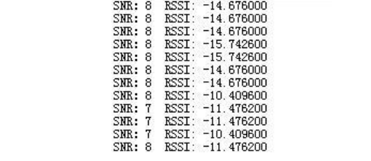
SNR: Signal-to-Noise Ratio (greater values indicate greater stability), RSSI: Received Signal Strength Indication (greater values indicate greater stability).
Communication Modes
- Transparent Transmission: For example, device A sends 5 bytes of data "AA BB CC DD EE" to device B, and device B receives the data as "AA BB CC DD EE" (transparent transmission is for communication between devices with the same address and on the same communication channel; user data can be in character or hexadecimal format).
- Point-to-Point
- Point-to-Multipoint
- Broadcast Listening
- Directed Transmission: For example, device A (address: 0x1400, channel: 0x17) needs to send data "AA BB CC" to device B (address: 0x1234, channel: 0x10), the communication format is "12 34 10 AA BB CC," where 1234 is the address of module B and 10 is the channel, so module B can receive "AA BB CC." Similarly, if device B needs to send data "AA BB CC" to device A, the communication format is "14 00 17 AA BB CC," and device A can receive "AA BB CC" (directed transmission allows communication between devices with different addresses and communication channels; data format is hexadecimal, with the format being high address + low address + channel + user data).
- Point-to-Multipoint
- Broadcast Listening
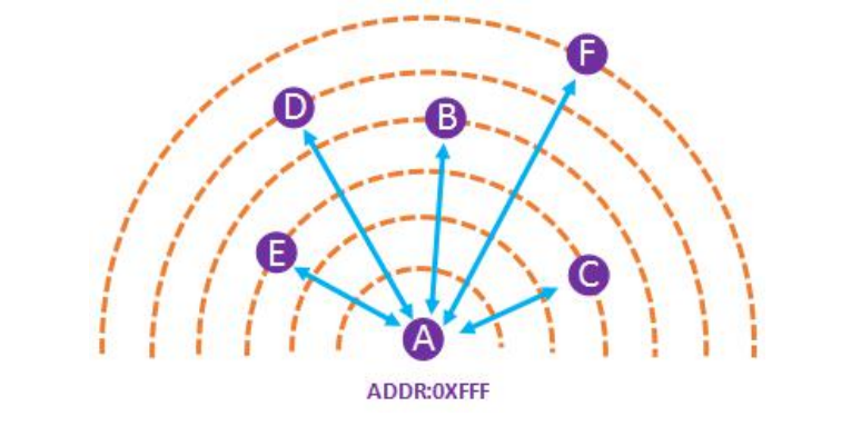
Broadcast and Data Monitoring: By setting the module address to 0xFFFF, you can monitor the data transmission of all modules on the same channel. The data sent can be received by modules with any address on the same channel, serving the purpose of broadcasting and monitoring.
Transparent Transmission Mode
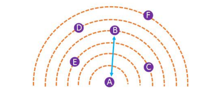
Point-to-Point

- Two modules with the same address, channel, and wireless rate (non-serial port baud rate) can engage in point-to-point communication. One module sends while the other receives (one must transmit, and the other must receive).
- Each module can send and receive.
- Data transmission is entirely transparent, what you send is what you get.
| Transmitting Module | Receiving Module | |
|---|---|---|
| Quantity | 1 | 1 |
| Content | Data | Data |
For example:
Devices A and B both have the address 0x1234, channel 0x12, and the same rate.
Device A sends: AA BB CC DD
Device B receives: AA BB CC DD
The transparent transmission is quite straightforward, just treat the LoRa module as a serial port. Device A sends data through the serial port, and Device B can receive it via the serial port, and vice versa.
Point-to-Multi-Point
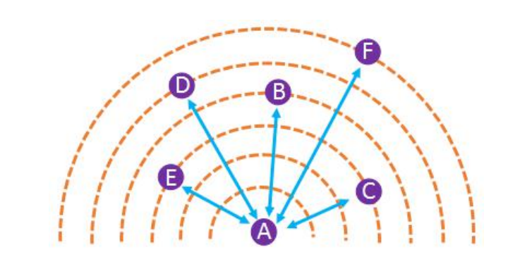
- Modules with the same address, channel, and wireless rate (non-serial port baud rate) can engage in point-to-multi-point communication. When one module sends, all other modules can receive.
- Each module can send and receive.
- Data transmission is entirely transparent, what you send is what you get.
| Transmitting Module | Receiving Module | |
|---|---|---|
| Quantity | 1 | N |
| Content | Data | Data |
The difference from point-to-point is that multiple modules can receive.
For example:
Devices A to F have the address 0x1234, channel 0x12, and the same rate.
Device A sends: AA BB CC DD
Devices B to F receive: AA BB CC DD
Broadcast Monitoring
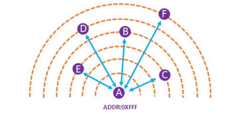
- If the module address is set to 0xFFFF, the module operates in broadcast monitoring mode. The data sent can be received by all other modules with the same rate and channel (broadcast), and it can also monitor data transmission from all modules on the same rate and channel (monitoring).
- Broadcast monitoring does not require the same address.
| Transmitting Module | Receiving Module | |
|---|---|---|
| Quantity | 1 | N |
| Content | Data | Data |
The difference from point-to-multi-point is that the addresses can be different.
For example:
Device A has an address of 0xFFFF, and Devices B to F have different addresses. Devices B and C have the address 0x1234, and Devices D, E, and F have the address 0x5678. All devices A to F have the same rate.
Broadcast:
Device A broadcasts: AA BB CC DD
Devices B to F receive: AA BB CC DD
Monitoring:
Device B sends to C: AA BB CC DD
Device A monitors: AA BB CC DD
Device D sends to E and F: 11 22 33 44
Device A monitors: 11 22 33 44
Directed Transmission Mode
Point-to-Point
- When sending, the module can modify the address and channel, allowing users to specify data transmission to any address and channel.
- It can achieve networking and relay functions.
| Transmitting Module | Receiving Module | |
|---|---|---|
| Quantity | 1 | 1 |
| Content | Address + Channel + Data | Data |
The difference from point-to-point transparent is that the module address and channel can change, but the rate remains the same.
Sure, here's the text translated into English while preserving the original markdown format:
For example:
Device A address 0x1234, channel 0x17;
Device B address 0xABCD, channel 0x01;
Device C address 0x1256, channel 0x13.
Device A sends: AB CD 01 AA BB CC DD
Device B receives: AA BB CC DD
Device C receives: None
Device A sends: 12 56 13 AA BB CC DD
Device B receives: None
Device C receives: AA BB CC DD
#### Codeless Testing
Prepare 2 USB to TTL converters and 2 LoRa modules. Connect them separately to USB to TTL (power, common ground, TX/RX pairing). Connect the MD0 pins of the two LoRa modules to VCC, then plug them into the computer's USB ports. Open the configuration software and set the following parameters:
Device A:
- Normal mode
- Directed transmission
- **Baud rate: 115200 (must be 115200)**
- Parity: None
- Air rate: 19.2k
- Sleep time: 1s
- **Module address: 0**
- **Communication channel: 0**
- Transmit power: 20dBm
Device B:
- Normal mode
- Directed transmission
- **Baud rate: 115200 (must be 115200)**
- Parity: None
- Air rate: 19.2k
- Sleep time: 1s
- **Module address: 65534**
- **Communication channel: 10**
- Transmit power: 20dBm
After configuration, click "Save Configuration," then **remove MD0 and power off**.
Power both modules back on, open the configuration software, and check "HEX" (hexadecimal) for both transmit and receive.
In the transmit area of A, enter `FF FE 0A 11 12 13 14`, click send, and you'll receive `11 12 13 14` in B's receive area. Or, in B's transmit area, enter `00 00 00 11 12 13`, and you'll receive `11 12 13` in A's receive area.
Here, `FF FE` represents B's address 65534 in hexadecimal, the channel is 10 (in hexadecimal, it's `0A`), and the content data is `11 12 13 14`. Similarly, B's transmitted data includes A's address `00 00`, channel `00`, and content `11 12 13`. The data transmission format is **high-byte address + low-byte address + channel + user data**.
#### Code-based Testing
Point-to-point fixed transmission only adds address bytes compared to point-to-point transparent transmission. You can define it like this:
```c title="main.c"
/* USER CODE BEGIN PV */
uint8_t B_Addr[2] = { 0xFF, 0xFE };
uint8_t B_Chan[1] = { 0x0A };
/* USER CODE END PV */
```
After configuring the code with UART (HAL library environment), send the address bytes before each data transmission:
This way, the receiving device (Device B) can receive a data frame sent by A (without the address bytes).
Broadcast Listening
- When the module address is 0xFFFF, the module is in broadcast listening mode. The data it sends can be received by all other modules with the same speed and channel (broadcast). It can also listen to data transmission from all modules on the same speed and channel (listening).
- Broadcast listening doesn't require the same address.
- The channel address can be set. When the address is 0xFFFF, it's in broadcast mode; for other addresses, it's in directed transmission mode.
| Sending Module | Receiving Modules | |
|---|---|---|
| Quantity | 1 | N |
| Transmission Content | 0xFFFF + channel + data | Data |
Please let me know if you need any further assistance or clarification.

```markdown
Device A Address 0xFFFF Channel 0x12;
Devices B and C Address 0x1234, Channel 0x13;
Device D Address 0xAB00, Channel 0x01;
Device E Address 0xAB01, Channel 0x12;
Device F Address 0xAB02, Channel 0x12;

Device A Broadcasts: FF FF 13 AA BB CC DD
Devices B and C Receive: AA BB CC DD

Device A Sends: AB 00 01 11 22 33 44
Only Device D Receives: 11 22 33 44

Device E Sends: AB 02 12 66 77 88 99
Device F Receives: 66 77 88 99
Device A Listens: 66 77 88 99

## References and Acknowledgments

- [LORA Module ATK-LORA-01](http://www.openedv.com/docs/modules/iot/atk-lora-01.html)
- [ELECFREAKS LORA Module ATK-LORA User Guide](https://www.bilibili.com/video/BV1D44y1t7bn)
- [ELECFREAKS Product Information - LORA Module ATK-LORA-01 Data Download and Technical Discussion](http://www.openedv.com/thread-309019-1-1.html)
- [Testing Method for Two LORA Modules Working in General Mode for Directional Data Transmission (Using Host Computer Testing)](http://www.openedv.com/forum.php?mod=viewthread&tid=288951)
- [ATK-LORA-01 Wireless Serial Module Receiving Only 00](http://www.openedv.com/forum.php?mod=viewthread&tid=328190&highlight=ATK-LORA-01)

> Original: <https://wiki-power.com/>
> This post is protected by [CC BY-NC-SA 4.0](https://creativecommons.org/licenses/by/4.0/deed.en) agreement, should be reproduced with attribution.
Note: The text has been translated into colloquial, professional, and elegant English while maintaining the original markdown format.
This post is translated using ChatGPT, please feedback if any omissions.