Basic Electronic Components - Diode
Voltage-Current Characteristics:
- The forward voltage drop is approximately 0.7 V (LEDs are around 1-2 V with a current of 5-20 mA).
- It does not conduct in reverse bias, but if the reverse breakdown voltage is exceeded, it will conduct (exceeding the reverse maximum voltage may damage it).
- It doesn't conduct with a very low forward voltage (it only conducts when above 0.5 V).
Main Parameters of the Diode
- Maximum Forward Current \(I_F\): Represents the maximum average forward current allowed for continuous operation, exceeding which can lead to burning due to excessive junction temperature.
- Maximum Reverse Working Voltage \(U_R\): The maximum reverse voltage that can be applied, exceeding which may lead to breakdown. (\(U_R\) is usually half of the breakdown voltage)
- Reverse Current \(I_R\): The reverse current when not in breakdown; lower values indicate better conductivity.
- Maximum Operating Frequency \(f_M\): The upper cutoff frequency. Due to the junction capacitance effect, going beyond this frequency might not exhibit good unidirectional conductivity.
Classification of Diodes
Types:
- Rectifier Diodes
- Regular Diodes: Relatively slow recovery speed, not suitable for high-frequency circuits.
- Fast Recovery Diodes
- Schottky Diodes: Used in scenarios below 200V.
- Voltage Regulator Diodes: Sustain breakdown, suitable for low-power scenarios.
- Transient Voltage Suppressors (TVS): Provide instant breakdown, used in high-power scenarios.
Rectifier Diodes
Purpose: Utilize unidirectional conduction to convert AC into pulsating DC.
Fast Recovery Diodes (FRD)
The structure and function of fast recovery diodes are the same as rectifier diodes. Rectifier diodes are used in low-frequency applications below 500 Hz, while FRDs are used in high-frequency switching applications ranging from several kHz to 100 kHz. Therefore, FRDs have very short reverse recovery time (trr), which is crucial for high-speed switching. Generally, the trr of regular rectifier diodes is a few microseconds to tens of microseconds, while the trr of FRDs ranges from tens of milliseconds to hundreds of milliseconds, approximately 1/100th of regular rectifier diodes. They are used in switch-mode power supplies, inverters, DC/DC converters, and more.
Voltage Regulator (Zener) Diodes
Definition: Diodes that can maintain a constant voltage.
Voltage regulator diodes utilize the reverse characteristics of the PN junction. They continuously break down and maintain a constant voltage, suitable for low-power scenarios.
Regulation conditions:
- Operating in the breakdown state.
- Reverse voltage greater than the regulation voltage.
Parameters of voltage regulator diodes:
- Regulation Voltage \(U_Z\): Represents the breakdown voltage at a specified current. For the same model of regulator diode, the regulation voltage is a fixed value.
- Reverse Current \(I_Z\): The reference current when operating in the regulation state; the regulation effect deteriorates when the current falls below this value, also known as \({I_Z}_{min}\).
- Rated Power Dissipation \(P_{ZM}\): Equals the product of the regulation voltage \(U_Z\) and the maximum regulation current \(I_{ZM}\). Exceeding this value may lead to damage due to high junction temperature. As long as the rated power is not exceeded, a higher current results in better regulation.
Basic voltage regulation circuit:
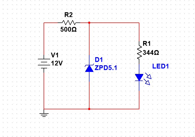
Choice of current-limiting resistor:
In the voltage regulation circuit, a current-limiting resistor is connected in series to protect the voltage regulator diode (to drop the voltage difference between input voltage and regulation voltage). The voltage across the resistor is the difference between the input voltage and the regulation voltage, and the current is the sum of \({I_Z}_{min}\) and \({I_Z}_{max}\) of the voltage regulator diode, plus the total current of the load circuit.
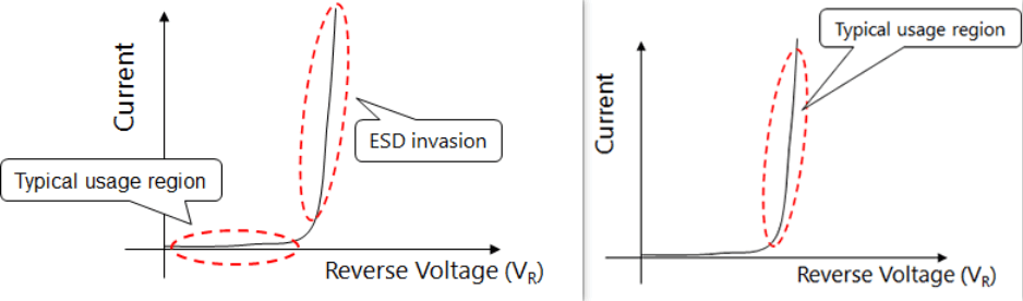
Transient Voltage Suppressors (TVS)
TVS diodes are used to prevent transient high-energy surges and protect sensitive components. TVS diodes can be unidirectional or bidirectional. The characteristics of unidirectional TVS diodes are similar to voltage regulator diodes, and bidirectional TVS diodes are essentially two voltage regulator diodes connected in reverse.
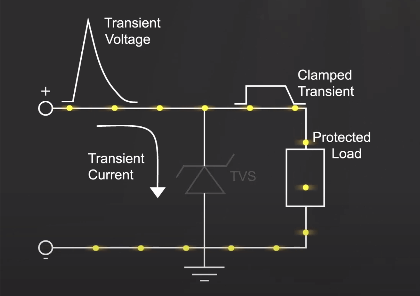
TVS diodes are connected in parallel in the circuit. Under normal circumstances, current does not flow through the TVS branch, and the TVS exhibits the unidirectional conduction characteristic of a diode:
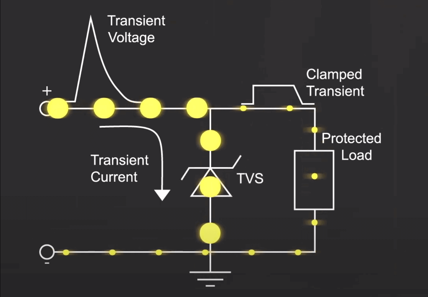
When an overvoltage occurs, the TVS enters breakdown and diverts the current to the ground, keeping the voltage of the subsequent circuit at the clamping voltage of the diode:
Applications:
- Placed on signal and power lines to protect against electrostatic discharge, AC surges, or noise.
- Can handle pulses exceeding 10,000 V and 60 A for a continuous duration of 10 ms, protecting against component damage or interference caused by bus switching.
- Placed between signal lines and ground to prevent data and control lines from being affected by noise.
Main parameters of TVS diodes:
- 反向截止电压 VRWM y corriente inversa de fuga IR: VRWM representa la tensión máxima a la que el diodo TVS deja de conducir, a esta tensión, solo hay una pequeña corriente inversa de fuga IR.
- Tensión de ruptura VBR: La tensión a la que el diodo TVS comienza a conducir cuando se le aplica una corriente de prueba especificada, esto marca el punto de inicio de la conducción del diodo TVS.
- Corriente máxima de pico IPP: Esta es la corriente de pico máxima permitida a través del diodo TVS cuando se le aplica un pulso de 10/1000 μs (la corriente de pico para un pulso de 8/20 μs es aproximadamente cinco veces mayor que la corriente de pico para este tipo de pulso). Exceder esta corriente puede resultar en daño permanente. En una serie dada, los diodos con una tensión de ruptura más alta permiten corrientes de pico más pequeñas, generalmente en el rango de varios amperios a decenas de amperios.
- Tensión de pinzamiento máxima VC: Es la tensión que aparece en los extremos del diodo TVS cuando fluye la corriente de pico máxima IPP.
- Potencia de pico del pulso Pm: Pm = IPP * VC. Con una tensión de pinzamiento máxima dada, una mayor potencia Pm indica una mayor capacidad para soportar corrientes transitorias. Con una potencia Pm dada, una tensión de pinzamiento más baja indica una mayor capacidad para soportar corrientes transitorias.
- Potencia en estado estable P0: El diodo TVS también se puede utilizar como un diodo de regulación en estado estable, en este caso se utiliza la potencia en estado estable.
- Capacitancia interelectrodos Cj: Al igual que la resistencia varistora, la capacitancia interelectrodos Cj de un diodo TVS es relativamente alta, y es mayor en diodos unidireccionales que en diodos bidireccionales. Además, la capacitancia interelectrodos es mayor en diodos de mayor potencia y afecta el tiempo de respuesta del diodo TVS.
Diferencias entre el diodo TVS y el diodo Zener de regulación:
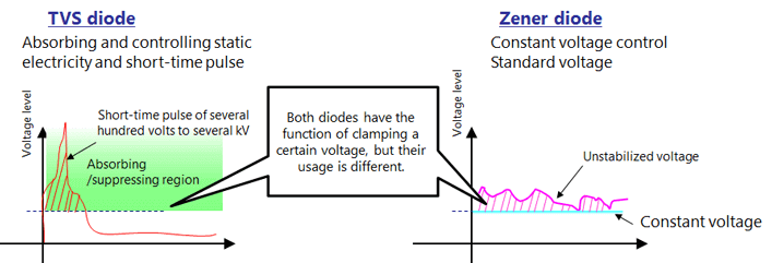
El diodo TVS absorbe sobretensiones muy altas en un corto período de tiempo para proteger los circuitos posteriores, mientras que el diodo Zener de regulación limita la tensión de entrada a un valor constante y proporciona esa tensión constante a los circuitos posteriores.
Diodo de conmutación
Diodo diseñado para aplicaciones de conmutación, con un tiempo de conmutación corto entre el estado de corte y el estado de conducción, evitando así daños por corriente inversa en componentes delicados.
Ejemplo:
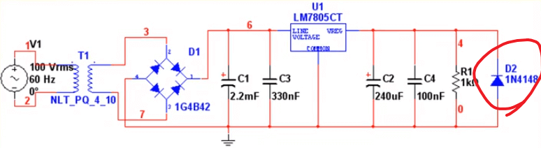
El diodo 1N4148 en la figura cumple una función protectora: cuando se aplica una tensión negativa en el lado derecho, conduce a tierra para proteger el regulador de tres terminales.
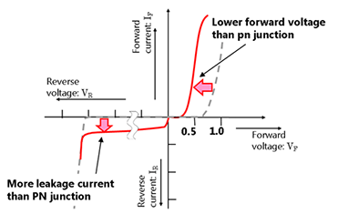
Diodo Schottky (SBD)
El diodo Schottky es un dispositivo que combina semiconductores y metal en lugar de utilizar una unión PN. Tiene una baja tensión directa y un tiempo de recuperación inversa corto, por lo que es adecuado para aplicaciones de conmutación de alta velocidad.
Características V-I del diodo Schottky:
Polarización directa e inversa
- Polarización directa: Significa que el terminal P se conecta a un potencial alto, y el terminal N se conecta a un potencial bajo, lo que permite que la corriente fluya en la dirección de la unión PN, mostrando sus propiedades de conducción unidireccional.
- Polarización inversa: En cambio, genera una corriente inversa que fluye desde la región N hacia la región P. Por lo general, se considera que en la polarización inversa, la unión PN no conduce, y en su mayoría se encuentra en un estado de corte.
Encapsulados comunes
| Nombre del encapsulado | Observaciones |
|---|---|
| DO-214AC/SMA | Capacidad de corriente de 2 A |
| DO-214AA/SMB | Capacidad de corriente de 4 A |
| DO-214AB/SMC | Capacidad de corriente de 5 A |
| DPAK/D2PAK |
Referencias y Agradecimientos
(Sin cambios)
- Guía de selección de diodos (solo como referencia)
- Dispositivos semiconductores discretos - Capítulo II: Diodos
- Rendimiento y selección de diodos TVS
- Notas de un ingeniero electrónico: Guía de selección de diodos
[Texto a ser reemplazado[1]] [Texto a ser reemplazado[2]]
Este post está traducido usando ChatGPT, por favor feedback si hay alguna omisión.